IS620P User Manual Chapter 4 Running and Commissioning
- 83 -
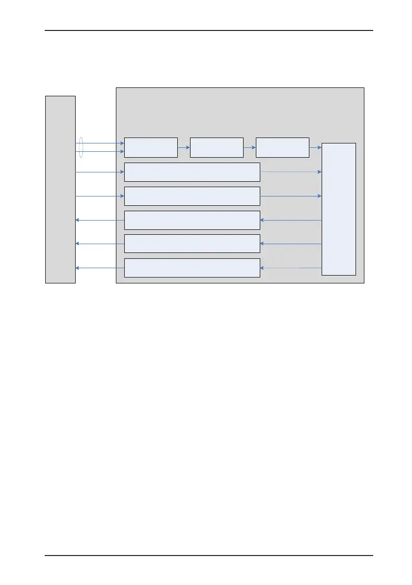
4.2 Use of the Speed Control Mode
Figure 4-5 Diagram of the speed control mode
Reference input
setting
Speed
regulator
Host
controller
Speed
reference
input
H06-00 Main speed
reference A source
H06-01 Auxiliary speed
reference B source
H06-02 Speed
reference selection
H06-05 Acceleration ramp
time constant of speed
reference
H06-06
Deceleration ramp
time constant of speed
reference
H06-07 Maximum speed threshold
H06-08 Forward speed threshold
H06-09 Reverse speed threshold
H06-17 Speed
consistent signal threshold
Reference ramp Reference limit
Reference direction selection
SPDDirSel input
ZCLAMP input
Speed threshold for zero clamp
(H06
-15)
Rotational speed limit output
V-CMP output
Speed consistent output
Servo drive
H06-18 Threshold of
speed reached signal
Speed reached output
V-ARR output
V-LT output
The main use procedure of the speed control mode is as follows:
1. Connect the power cables of the main circuit and control circuit of the servo drive, motor
power cables, and encoder cables correctly. After power-on, the keypad of the servo drive
displays "rdy", indicating that the wiring is correct.
2. Perform trial jog running by pressing keys and ensure that the motor can run properly.
3. Connect the required DI/DO signals and analog speed references of terminal CN1
according to Figure 4-6.
4. Perform the setting related to the speed control mode.
5. Make the motor rotate at a low speed and ensure that the rotating direction is normal.
Then, adjust the gain. For details, see the commissioning procedure in section 4.5.

 Loading...
