Chapter 3 Wiring of Servo System IS620P User Manual
- 54 -
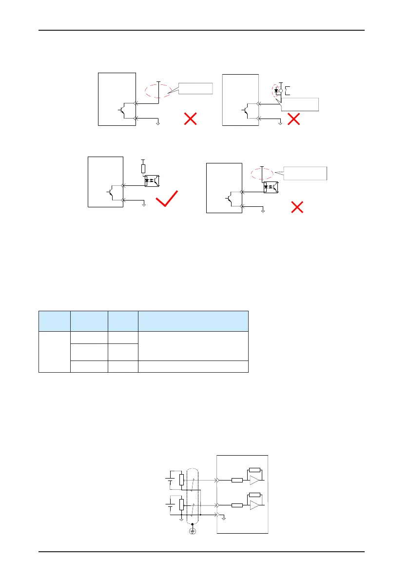
The following gures are examples of wrong connection.
Servo drive
DO1-
DO1+
6
7
5-24 VDC
No relay
connected
Servo drive
Relay
DO1-
DO1+
6
7
5-24 VDC
Wrong polarity of
flywheel diode
b) When input signal of the upper device is optocoupler input:
Servo drive
DO1-
DO1+
6
7
5-24 VDC
Opto-coupler
Servo drive
DO1-
DO1+
6
7
5-24 VDC
Opto-coupler
No current-limit
resistor connected
The maximum allowable voltage and current of the optocoupler output circuit inside the
servo drive are as below:
Maximum voltage: 30 VDC
Maximum current: DC 50 mA
3.3.2 AI Signals
Table 3-13 AI signal description
Signal
Default
Function
Pin No. Function Description
Analog
AI2 18
Common analog input signals:
Resolution: 12 bit
Input voltage: maximum ±12V
AI1 20
GND 19 Analog input signal ground
Speed and torque analog signal input terminals are AI1 and AI2, resolution of which is 12 bit.
Corresponding voltage values are set via parameters of H03 group.
Input voltage range: -10 to +10 V; resolution: 12 bit;
Maximum allowable voltage: ±12 V;
Input impedance: ≈ 9 kΩ
AI1
Servo drive
≈
9 kΩ
20
≈ 9 kΩ
19
GND
AI2 18
-10 to 10 V
-10 to 10 V

 Loading...
