IS620P User Manual Chapter 4 Running and Commissioning
- 75 -
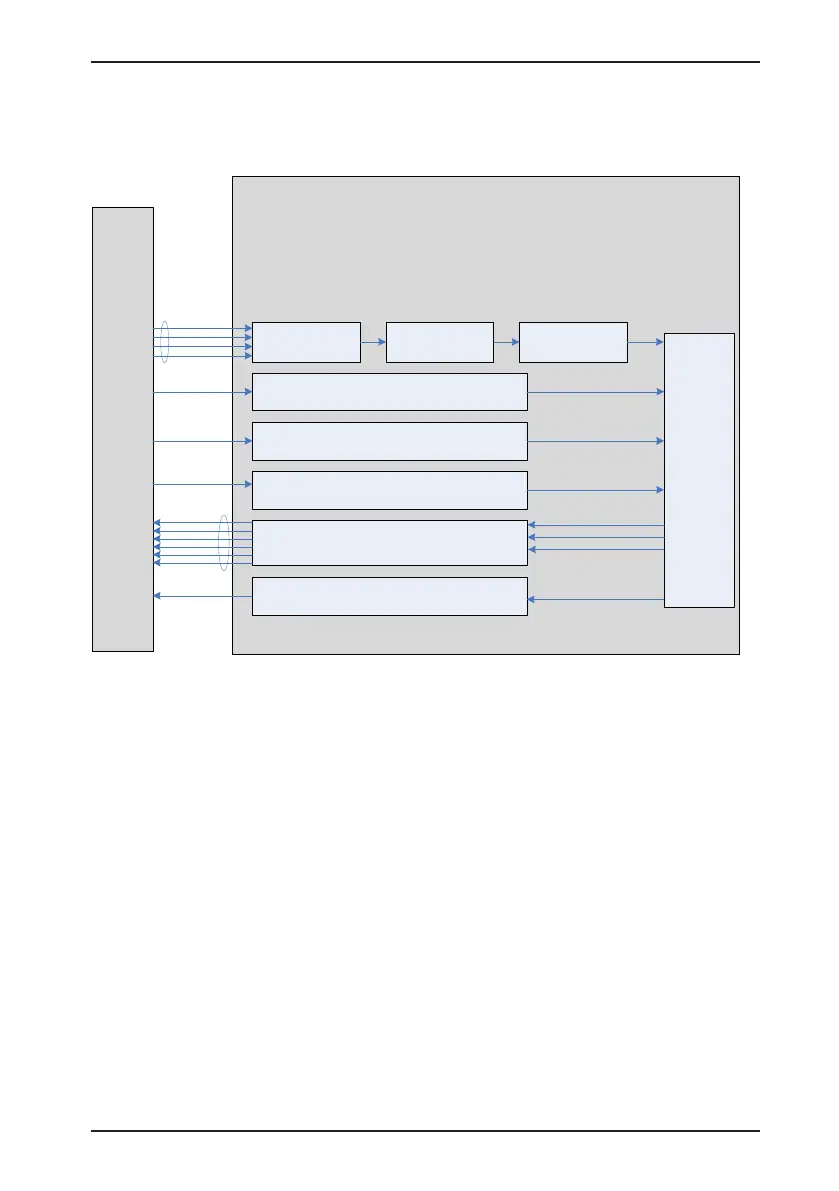
4.1 Use of the Position Control Mode
Figure 4-1 Diagram of the position control mode
Reference input
setting
Position
regulator
Host
controller
Pulse input
H05-00 Position
reference source
H05-01 Pulse reference
input terminal selection
H05-15 Pulse reference
form
H
05-
07 Electronic gear ratio 1
(numerator)
H05-09 Electronic gear ratio 1
(
denominator)
H
05-11
Electronic gear ratio 2
(numerator)
H05-13 Electronic gear ratio 2
(denominator)
H05-02 Pulses for one motor
revolution
H05-04 First-order low-
pass filter time constant
H05-06 Filter time
constant of average value
of position references
H05-20 Output condition of positioning
completed signal (COIN)
H05-
21 Threshold for positioning
completed
Electronic gear
ratio
Position
reference filter
Reference direction selection
POSDirSel
input
INHIBIT
input
Frequency-division output
Frequency-
division pulse
output
Pulse input forbidden
Position deviation cleared
COIN output
Positioning completed
Servo drive
H05-17 Encoder
frequency-division pulses
H05-38 Servo pulse
output source
CLR input
The position control mode is the most common mode of the servo drive. The main use
procedure is as follows:
1. Connect the power cables of the main circuit and control circuit of the servo drive, motor
power cables, and encoder cables correctly. After power-on, the keypad of the servo drive
displays "rdy", indicating that the wiring is correct.
2. Perform trial jog running by pressing keys and ensure that the motor can run properly.
3. Connect the signals of terminal CN1, such as the pulse direction input, reference pulse
input, and required DI/DO signals (servo drive enabled and positioning completed)
according to Figure 4-2.
4. Perform the setting related to the position control mode. Set the DI/DO functions in groups
H03 and H04 based on actual requirements. You may also need to set the home return
and frequency-division functions based on actual requirements.
5. Enable the servo drive. Send a position reference from the host controller to enable
the servo motor to rotate. Make the motor rotate at a low speed and check whether the
rotating direction and electronic gear ratio are normal. Then, adjust the gain. For details,
see the commissioning procedure in section 4.5.

 Loading...
