Chapter 1 Servo System Selection IS620P User Manual
- 8 -
Observe the following precautions during wiring:
Note 1: Remove the jumper between terminals
and D of the servo drive before connecting
a regen resistor.
Note 2: CN3 and CN4 are two same communication ports, which can be used at random.
Note 3: For the single-phase 220 V servo drive, the main circuit terminals are L1 and L2.
Never wire the reserved terminal.
1.1 Designation Rules of the Servo Motor and Servo Drive
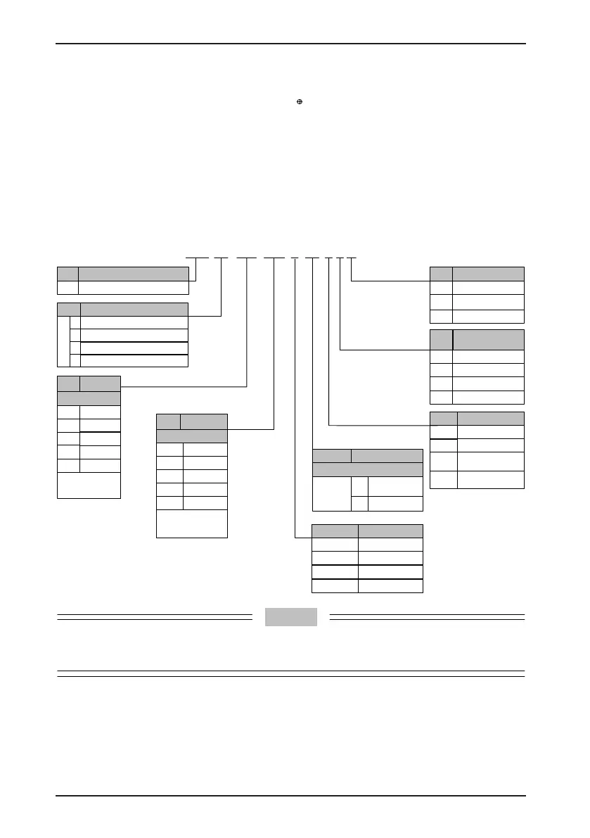
Figure 1-3 Designation rules of the servo motor
ISM H1-75B 30C B-U2 3 1 X
H
Low inertia, small capacity
Low inertia, medium capacity
Mark Feature
Medium inertia, medium capacity
Low inertia, small capacity
Mark Encoder Type
1 letter + 1 digit
20-bit bus type
U
2
1
Mark
Rated
Power (W)
1 letter + 2 digits
A
x 1
B
x 10
C
x 100
D
x 1000
E
x 10000
Mark Series
ISM
ISM series servo motor
1
2
3
4
Example
75B: 750 W
15C: 1500 W
Mark
Rated Speed
(RPM)
1 letter +
2 digits
A
x 1
B
x 10
C
x 100
D
x 1000
E
x 10000
Example
15B: 150 RPM
30C: 3000 RPM
Mark Voltage Class
A
110 V
B
220 V
Mark Shaft Connection
1
Optical shaft
3
Solid with key and
threaded hole
2
Solid with key
5
Solid with threaded
hole
Mark Brake, Gear, Oil Seal
0
None
1
With oil seal
2 With brake
4
With oil seal + brake
Mark Customized Feature
X
Natural cooling
Y
Aviation plug
connection
2500-PPR
incremental
Z
2nd generation motor
C
D
300 V
380 V
Models ending in –U231* and –U234 * are standard models. Prior ordering is required for non-
standard models.
ISMH2-20C/25C/30C/40C/50C are not congured with a brake now.

 Loading...
