Connector/Header Locations and Pin-outs Intel® Server Boards S5520HC, S5500HCV, and S5520HCT TPS
Revision 1.8
Intel order number E39529-013
108
6. Connector/Header Locations and Pin-outs
6.1 Board Connector Information
The following section provides detailed information regarding all connectors, headers, and
jumpers on the server boards.
The following table lists all connector types available on the board and the corresponding
preference designators printed on the silkscreen.
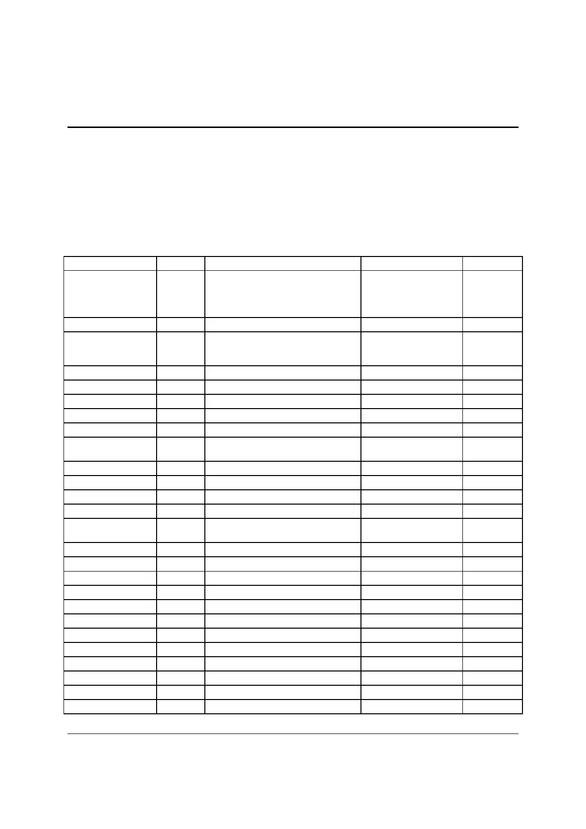
Table 46. Board Connector Matrix
Connector Quantity Reference Designators Connector Type Pin Count
Power supply 4
J1K3
J9A1
J9K1
J9K2
Main power
CPU 1 power
CPU 2 Power
P/S aux/IPMB
24
8
8
5
CPU 2 U7J1, U7C1 CPU sockets 1366
Main memory 12
J4F1, J5F1*, J5F2, J5F3*, J6F1,
J6F2*, J8F1, J8F2, J8F3, J9F1, J9F2,
J9F3
DIMM sockets 240
PCI Express* x8 4 J2B1, J2B2, J3B1, J4B1* Card edge
PCI Express* x16 1 J4B2 Card edge
32-bit PCI 1 J1B2, Card edge
Intel
RMM3 1 J1C1 Mezzanine 34
SAS Module Slot 1 J2J1 Mezzanine 50
SATA Software RAID
5 Key
1 J1F2 Key holder 3
System fans 4 J1K1, J1K2, J1K4, J1K5 Header 6
System fans 1 J9A2 Header 4
CPU fans 2 J7K1, J9A3 Header 4
Battery 1 BT5B1 Battery holder 3
Stacked RJ45/2xUSB 2 J5A1, J6A1
External LAN built-in
magnetic and dual USB
22
Video 1 J7A1 External DSub 15
Serial port A 1 J8A1 External DB9 9
Serial port B 1 J1B1 Header 9
Front panel 1 J1B3 Header 24
Internal USB 2 J1D1, J1D2 Header 10
USB Solid State Drive 1 J2D2 Low profile header 10
Internal USB 1 J1H2 Header 4
Chassis Intrusion 1 J1F6 Header 2
Serial ATA 6 J1G1, J1G4, J1G5, J1E3, J1F1, J1F4 Header 7
HSBP 2 J1F5, J1G3 Header 4
SATA SGPIO 1 J1G2 Header 4
LCP/IPMB 1 J1G6 Header 4

 Loading...


