Intel® Server Boards S5520HC, S5500HCV, and S5520HCT TPS Connector/Header Locations and Pin-outs
Revision 1.8
Intel order number E39529-013
109
Connector Quantity Reference Designators Connector Type Pin Count
Configuration jumpers 4
J1E6 (CMOS Clear), J1E2 (ME Force
Update), J1E4 (Password Clear), J1E5
(BIOS Recovery), J1H1 (BMC Force
Update),
Jumper 3
HDD Led 1 J1E1 Header 2
* Empty on Intel
®
Server Board S5500HCV.
6.2 Power Connectors
The main power supply connection uses an SSI-compliant 2x12 pin connector (J1K3).
Three additional power-related connectors also exist:
Two SSI-compliant 2x4 pin power connectors (J9A1, J9K1) to provide 12-V power to the
CPU voltage regulators and memory.
One SSI-compliant 1x5 pin connector (J9K2) to provide I
2
C monitoring of the power
supply.
The following tables define these connector pin-outs.
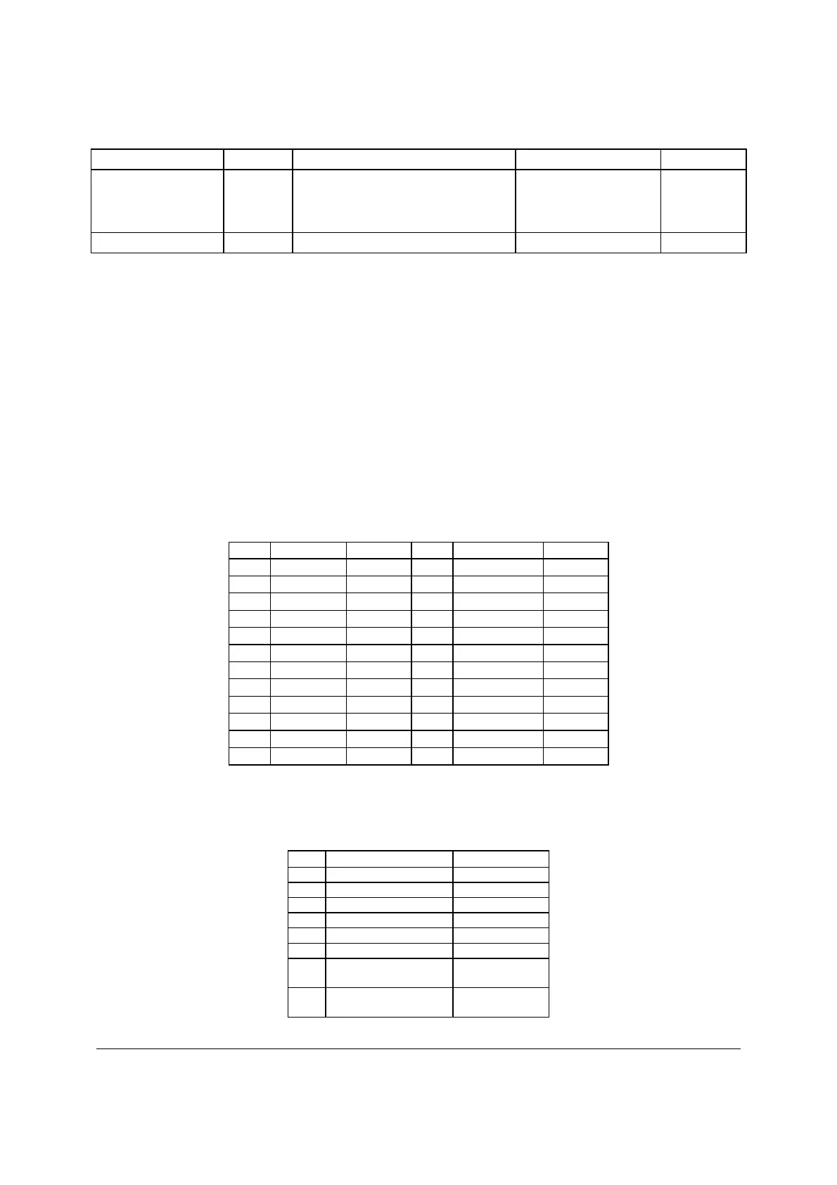
Table 47. Main Power Connector Pin-out (J1K3)
Pin Signal Color Pin Signal Color
1 +3.3 Vdc Orange 13 +3.3 Vdc Orange
2 +3.3 Vdc Orange 14 -12 Vdc Blue
3 GND Black 15 GND Black
4 +5 Vdc Red 16 PS_ON# Green
5 GND Black 17 GND Black
6 +5 Vdc Red 18 GND Black
7 GND Black 19 GND Black
8 PWR_OK Gray 20 RSVD_(-5 V) White
9 5 VSB Purple 21 +5 Vdc Red
10 +12 Vdc Yellow 22 +5 Vdc Red
11 +12 Vdc Yellow 23 +5 Vdc Red
12 +3.3 Vdc Orange 24 GND Black
Table 48. CPU 1 Power Connector Pin-out (J9A1)
Pin Signal Color
1 GND of Pin 5 Black
2 GND of Pin 6 Black
3 GND of Pin 7 Black
4 GND of Pin 8 Black
5 +12 Vdc CPU1 Yellow/black
6 +12 Vdc CPU1 Yellow/black
7 +12 Vdc
DDR3_CPU1
Yellow/black
8 +12 Vdc
DDR3_CPU1
Yellow/black

 Loading...


