Home
Intel
Server Board
BB5520UR
Intel BB5520UR User Manual
5
of 1
of 1 rating
190 pages
Give review
Manual
Specs
To Next Page
To Next Page
To Previous Page
To Previous Page
Loading...
Intel® Server Boards S5520HC, S5500HCV,
and S
5520HCT TPS
Functional Architecture
Revision 1.8
Intel order number E39529-013
57
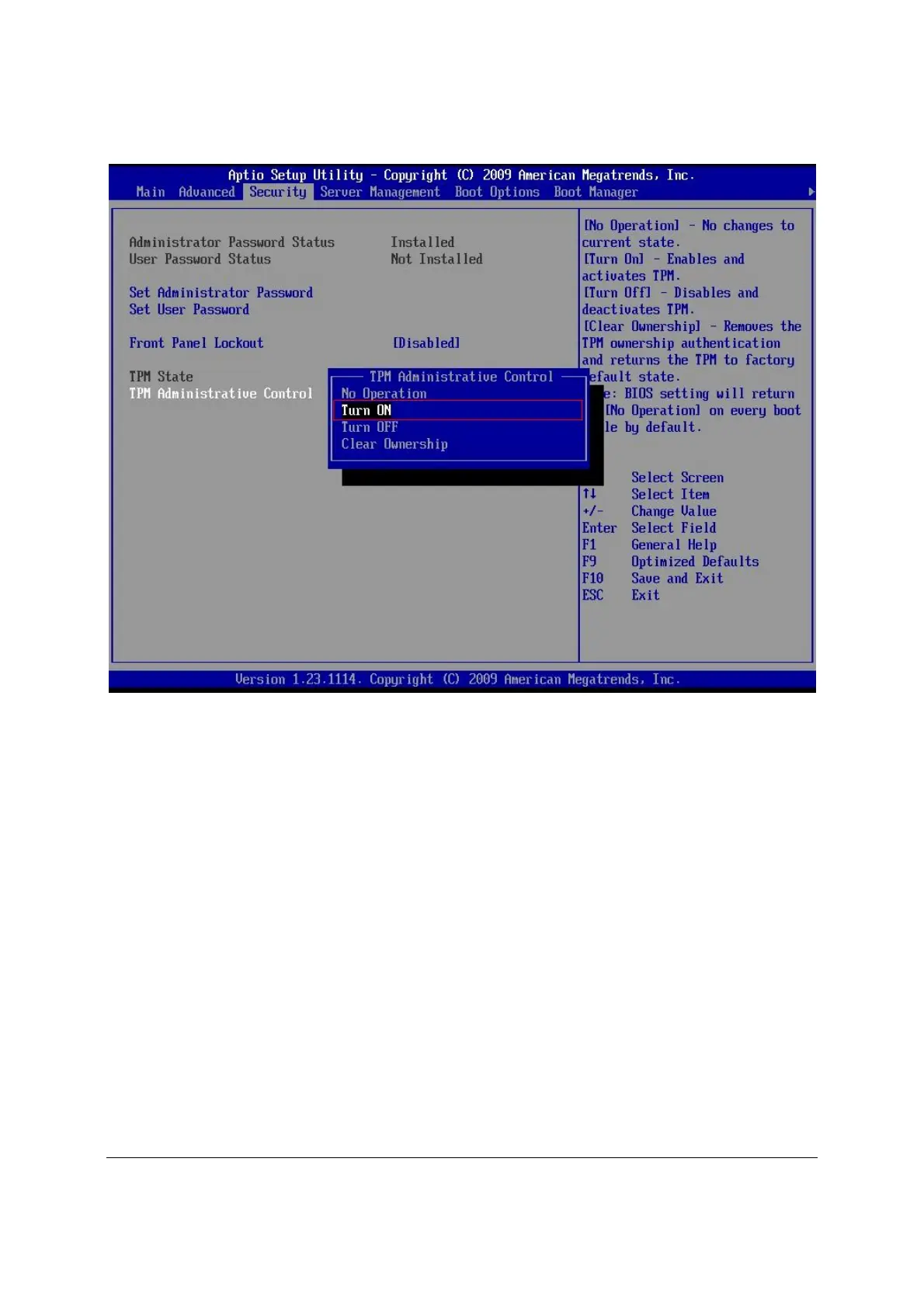
Figure 23. Activating TPM
4. Go to BIO
S setup Me
nu,
Security
Tab, TPM State should be
“
Enabled & Activated
”.
70
72
Table of Contents
Default Chapter
2
Revision History
2
Table of Contents
4
1 Introduction
15
Chapter Outline
15
Server Board Use Disclaimer
15
2 Overview
16
Intel Server Boards S5520HC, S5500HCV and S5520HCT Feature Set
16
Server Board Connector and Component Layout
19
Figure 1. Intel Server Board S5520HC
19
Figure 2. Intel Server Board S5500HCV
19
Figure 3. Major Board Components
21
Server Board Mechanical Drawings
22
Figure 4. Mounting Hole Locations
22
Figure 5. Major Connector Pin-1 Locations (1 of 2)
23
Figure 6. Major Connector Pin-1 Locations (2 of 2)
24
Figure 7. Primary Side Keep-Out Zone (1 of 2)
25
Figure 8. Primary Side Keep-Out Zone (2 of 2)
26
Figure 9. Primary Side Air Duct Keep-Out Zone
27
Figure 10. Primary Side Card-Side Keep-Out Zone
28
Figure 11. Second Side Keep-Out Zone
29
Server Board Rear I/O Layout
30
Figure 12. Rear I/O Layout
30
3 Functional Architecture
31
Figure 13. Intel Server Board S5520HC Functional Block Diagram
32
Figure 14. Intel Server Board S5500HCV Functional Block Diagram
33
Intel 5520 and 5500 I/O Hub (IOH)
34
Intel ® Quickpath Interconnect
34
PCI Express* Ports
34
Table 1. IOH High-Level Summary
34
Enterprise South Bridge Interface (ESI)
35
Manageability Engine (ME)
35
Controller Link (CL)
35
Processor Support
36
Processor Population Rules
36
Mixed Processor Configurations
36
Table 2. Mixed Processor Configurations
37
Intel ® Hyper-Threading Technology (Intel ® HT)
38
Enhanced Intel Speedstep Technology (EIST)
38
Intel ® Turbo Boost Technology
38
Execute Disable Bit Feature
38
Core Multi-Processing
39
Direct Cache Access (DCA)
39
Unified Retention System Support
39
Figure 15. Unified Retention System and Unified Back Plate Assembly
40
Memory Subsystem
41
Memory Subsystem Nomenclature
41
Figure 16. Intel
42
Figure 19. Intel
42
Supported Memory
43
Figure 17. Intel
43
Figure 18. Intel
43
Processor Cores, QPI Links and DDR3 Channels Frequency Configuration
44
Table 3. Memory Running Frequency Vs. Processor SKU
45
Table 4. Memory Running Frequency Vs. Memory Population
45
Publishing System Memory
46
Memory Interleaving
46
Memory Test
47
Memory Scrub Engine
47
Memory RAS
47
Memory Population and Upgrade Rules
48
Supported Memory Configuration
50
Table 5. Supported DIMM Population under the Dual Processors Configuration
51
Table 6. Supported DIMM Population under the Single Processor Configuration
51
Memory Error Handling
52
Ich10R
53
Serial ATA Support
53
Table 7. Onboard SATA Storage Mode Matrix
54
USB 2.0 Support
55
PCI Subsystem
56
PCI Express* Riser Slot (S5520HC - Slot 6)
57
Table 11. PCI Riser Support
57
Intel SAS Entry RAID Module AXX4SASMOD (Optional Accessory)
58
SAS RAID Support
59
Table 12. Intel SAS Entry RAID Module AXX4SASMOD Storage Mode
60
Baseboard Management Controller
61
BMC Embedded LAN Channel
62
Figure 20. Integrated BMC Hardware
62
3.10 Keyboard and Mouse Support
63
3.11 Video Support
63
Video Modes
63
Table 13. Serial B Header Pin-Out
63
Dual Video
64
Table 14. Video Modes
64
Floppy Disk Controller
63
Serial Ports
63
Network Interface Controller (NIC)
65
MAC Address Definition
65
Table 15. Onboard NIC Status LED
65
3.13 *Trusted Platform Module (TPM) - Supported Only on S5520HCT
66
Overview
66
TPM Security BIOS
66
Figure 21. Setup Utility - TPM Configuration Screen
68
Table 16. Tsetup Utility - Security Configuration Screen Fields
68
Txt)
69
Figure 22. Setting Administrator Password in BIOS
70
Figure 23. Activating TPM
71
Figure 24. TPM Activated
72
3.14 ACPI Support
73
Figure 25. BIOS Setting for TXT
73
Intel ® Virtualization Technology
74
Intel ® Virtualization Technology for Directed IO (VT-D)
74
4 Platform Management
75
Feature Support
75
IPMI 2.0 Features
75
Non-IPMI Features
75
Optional Advanced Management Feature Support
77
Enabling Advanced Management Features
77
Keyboard, Video, and Mouse (KVM) Redirection
77
Table 17. Basic and Advanced Management Features
77
Media Redirection
78
Web Services for Management (WS-MAN)
79
Embedded Web Server
80
Local Directory Authentication Protocol (LDAP)
80
Platform Control
81
Figure 26. Platform Control
81
Fan Speed Control
82
Memory Open and Closed Loop Thermal Throttling
82
Table 18. S5520HC, S5500HCV and S5520HCT Fan Domain Table
83
Intel ® Intelligent Power Node Manager
84
Manageability Engine (ME)
84
Figure 27. SMBUS Block Diagram
85
5 BIOS Setup Utility
86
Logo/Diagnostic Screen
86
BIOS Boot Popup Menu
86
Operation
86
Table 19. BIOS Setup Page Layout
87
Table 20. BIOS Setup: Keyboard Command Bar
88
Server Platform Setup Utility Screens
89
Figure 28. Setup Utility - Main Screen Display
90
Table 21. Setup Utility - Main Screen Fields
90
Figure 29. Setup Utility - Advanced Screen Display
92
Table 22. Setup Utility - Advanced Screen Display Fields
92
Figure 30. Setup Utility - Processor Configuration Screen Display
93
Table 23. Setup Utility - Processor Configuration Screen Fields
94
Figure 31. Setup Utility - Memory Configuration Screen Display
96
Table 24. Setup Utility - Memory Configuration Screen Fields
97
Figure 32. Setup Utility - Configure RAS and Performance Screen Display
98
Table 25. Setup Utility - Configure RAS and Performance Screen Fields
98
Figure 33. Setup Utility - Mass Storage Controller Configuration Screen Display
99
Table 8. Intel
99
Table 9. Intel
99
Table 26. Setup Utility - Mass Storage Controller Configuration Screen Fields
100
Figure 34. Setup Utility - Serial Port Configuration Screen Display
101
Table 27. Setup Utility - Serial Ports Configuration Screen Fields
101
Figure 35. Setup Utility - USB Controller Configuration Screen Display
102
Table 28. Setup Utility - USB Controller Configuration Screen Fields
103
Figure 36. Setup Utility - PCI Configuration Screen Display
104
Table 29. Setup Utility - PCI Configuration Screen Fields
104
Figure 37. Setup Utility - System Acoustic and Performance Configuration Screen Display
105
Figure 38. Setup Utility - Security Configuration Screen Display
106
Table 30. Setup Utility - System Acoustic and Performance Configuration Screen Fields
106
Table 31. Setup Utility - Security Configuration Screen Fields
107
Figure 39. Setup Utility - Server Management Configuration Screen Display
109
Table 32. Setup Utility - Server Management Configuration Screen Fields
109
Figure 40. Setup Utility - Console Redirection Screen Display
110
Table 33. Setup Utility - Console Redirection Configuration Fields
111
Figure 41. Setup Utility - Server Management System Information Screen Display
112
Table 34. Setup Utility - Server Management System Information Fields
112
Figure 42. Setup Utility - Boot Options Screen Display
113
Table 35. Setup Utility - Boot Options Screen Fields
114
Figure 43. Setup Utility - Add New Boot Option Screen Display
115
Table 36. Setup Utility - Add New Boot Option Fields
115
Figure 44. Setup Utility - Delete Boot Option Screen Display
116
Figure 45. Setup Utility - Hard Disk Order Screen Display
116
Table 37. Setup Utility - Delete Boot Option Fields
116
Table 38. Setup Utility - Hard Disk Order Fields
116
Figure 46. Setup Utility - CDROM Order Screen Display
117
Figure 47. Setup Utility - Floppy Order Screen Display
117
Table 39. Setup Utility - CDROM Order Fields
117
Table 40. Setup Utility - Floppy Order Fields
117
Figure 48. Setup Utility - Network Device Order Screen Display
118
Figure 49. Setup Utility - BEV Device Order Screen Display
118
Table 41. Setup Utility - Network Device Order Fields
118
Figure 50. Setup Utility - Boot Manager Screen Display
119
Table 42. Setup Utility - BEV Device Order Fields
119
Table 43. Setup Utility - Boot Manager Screen Fields
119
Figure 51. Setup Utility - Error Manager Screen Display
120
Figure 52. Setup Utility - Exit Screen Display
120
Table 44. Setup Utility - Error Manager Screen Fields
120
Table 45. Setup Utility - Exit Screen Fields
121
6 Connector/Header Locations and Pin-Outs
122
Board Connector Information
122
Table 46. Board Connector Matrix
122
Power Connectors
123
Table 47. Main Power Connector Pin-Out (J1K3)
123
Table 48. CPU 1 Power Connector Pin-Out (J9A1)
123
System Management Headers
124
Intel ® Remote Management Module 3 Connector
124
Table 49. CPU 2 Power Connector Pin-Out (J9K1)
124
Table 50. Power Supply Auxiliary Signal Connector Pin-Out (J9K2)
124
Table 51. Intel RMM3 Connector Pin-Out (J1C1)
124
LCP/IPMB Header
125
HSBP Header
125
SGPIO Header
125
Front Panel Connector
125
Table 52. LCP/IPMB Header Pin-Out (J1G6)
125
Table 53. HSBP Header Pin-Out (J1F5, J1G3)
125
Table 54. SGPIO Header Pin-Out (J1G2)
125
I/O Connectors
126
VGA Connector
126
Table 55. Front Panel SSI Standard 24-Pin Connector Pin-Out (J1B3)
126
Table 56. VGA Connector Pin-Out (J7A1)
126
NIC Connectors
127
SATA Connectors
127
SAS Module Slot
127
Table 57. RJ-45 10/100/1000 NIC Connector Pin-Out (J5A1, J6A1)
127
Table 58. SATA/SAS Connector Pin-Out (J1E3, J1G1, J1G4, J1G5, J1F1, J1F4)
127
Table 59. SAS Module Slot Pin-Out (J2J1)
127
Serial Port Connectors
128
Table 60. External DB9 Serial a Port Pin-Out (J8A1)
128
Table 61. Internal 9-Pin Serial B Header Pin-Out (J1B1)
128
USB Connector
129
Table 62. External USB Connector Pin-Out (J5A1, J6A1)
129
Table 63. Internal USB Connector Pin-Out (J1D1)
129
Table 64. Internal USB Connector Pin-Out (J1D2)
129
Fan Headers
130
Table 65. Pin-Out of Internal Low-Profile USB Connector for Solid State Drive (J2D2)
130
Table 66. Internal Type a USB Port Pin-Out (J1H2)
130
Table 67. SSI 4-Pin Fan Header Pin-Out (J7K1, J9A2, J9A3)
131
Table 68. SSI 6-Pin Fan Header Pin-Out (J1K1, J1K2, J1K4, J1K5)
131
7 Jumper Blocks
132
Figure 53. Jumper Blocks (J1E2, J1E4, J1E5, J1E6, J1H1)
132
Table 69. Server Board Jumpers (J1E6, J1E2, J1E4, J1E5, J1H1)
132
CMOS Clear and Password Reset Usage Procedure
133
Clearing the CMOS
133
Clearing the Password
133
BIOS Recovery Jumper
134
Force BMC Update Procedure
134
8 Intel Light Guided Diagnostics
136
5-Volt Stand-By LED
136
Figure 54. 5-Volt Stand-By Status LED Location
136
Fan Fault Led's
137
Figure 55. Fan Fault Led's Location
137
System ID LED and System Status LED
138
Figure 56. System Status LED Location
138
Table 70. System Status LED
139
DIMM Fault Leds
140
Figure 57. DIMM Fault Led's Location
140
Post Code Diagnostic Leds
141
Figure 58. POST Code Diagnostic LED Locations
141
9 Design and Environmental Specifications
142
Intel ® Server Boards S5520HC, S5500HCV, and S5520HCT Design Specifications128
142
Mtbf
142
Table 71. Server Board Design Specifications
142
Table 72. MTBF Estimate
143
Server Board Power Requirements
144
Figure 59. Power Distribution Block Diagram
144
Processor Power Support
145
Power Supply Output Requirements
145
Grounding
145
Stand-By Outputs
145
Table 73. Intel ® Xeon ® Processor Dual Processor TDP Guidelines
145
Table 74. 670-W Load Ratings
145
Remote Sense
146
Voltage Regulation
146
Dynamic Loading
146
Table 75. Voltage Regulation Limits
146
Capacitive Loading
147
Ripple/Noise
147
Timing Requirements
147
Table 76. Transient Load Requirements
147
Table 77. Capacitive Loading Conditions
147
Table 78. Ripple and Noise
147
Figure 60. Output Voltage Timing
148
Table 79. Output Voltage Timing
148
Figure 61. Turn On/Off Timing (Power Supply Signals)
149
Table 80. Turn On/Off Timing
149
Residual Voltage Immunity in Stand-By Mode
150
10 Regulatory and Certification Information
151
10.1 Product Regulatory Compliance
151
Product Safety Compliance
151
Product EMC Compliance - Class a Compliance
151
Certifications/Registrations/Declarations
152
10.2 Product Regulatory Compliance Markings
152
10.3 Electromagnetic Compatibility Notices
153
Fcc (Usa)
153
ICES-003 (Canada)
154
Europe (CE Declaration of Conformity)
154
VCCI (Japan)
154
BSMI (Taiwan)
154
RRL KCC (Korea)
155
Product Ecology Change (EU Rohs)
155
Product Ecology Change (Crohs)
155
China Packaging Recycle Marks (or GB18455-2001)
158
10.7 CA Perchlorate Warning
158
10.8 End-Of-Life/Product Recycling
158
Appendix A: Integration and Usage Tips
159
Appendix B: Compatible Intel Server Chassis
161
Table 81. Compatible Chassis/Heatsink Matrix
161
Figure 62. Active Processor Heatsink Installation Requirement
163
Appendix C: BMC Sensor Tables
164
Table 82. Integrated BMC Core Sensors
166
Appendix D: Platform Specific BMC Appendix
174
Table 10. Intel
174
Table 83. Platform Specific BMC Features
174
Appendix E: POST Code Diagnostic LED Decoder
175
Figure 63. Diagnostic LED Placement Diagram
175
Table 84. POST Progress Code LED Example
175
Table 85. POST Codes and Messages
176
Appendix F: POST Error Messages and Handling
179
Table 86. POST Error Messages and Handling
180
Table 87. POST Error Beep Codes
183
Table 88. BMC Beep Codes
183
Appendix G: Installation Guidelines
184
Glossary
186
Reference Documents
190
5
Based on 1 rating
Ask a question
Give review
Questions and Answers:
Need help?
Do you have a question about the Intel BB5520UR and is the answer not in the manual?
Ask a question
Intel BB5520UR Specifications
General
Brand
Intel
Model
BB5520UR
Category
Server Board
Language
English
Related product manuals
STL2 - Server Board Motherboard
24 pages
S5500BC - Server Board Motherboard
86 pages
S3420GPLC - Server Board Motherboard
144 pages
Intel S2600CW
210 pages
Intel S3000AH
21 pages
Intel S1200BTL
1 page
Intel S5000PSL
88 pages
Intel S3420GPRX
78 pages
Intel SE7501HG2
140 pages
Intel 5000 Series
170 pages
Intel S2600CP Family
223 pages
Intel S2600CO series
167 pages

 Loading...


