Connector/Header Locations and Pin-outs Intel® Server Boards S5520HC, S5500HCV, and S5520HCT TPS
Revision 1.8
Intel order number E39529-013
112
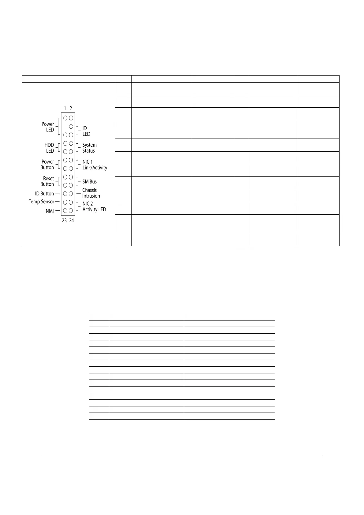
Table 55. Front Panel SSI Standard 24-pin Connector Pin-out (J1B3)
Pin Signal Name Description Pin
Signal Name Description
1 P3V3_STBY
(Power_LED_Anode)
Power LED + 2 P3V3_STBY Front Panel
Power
3 Key No Connection 4 P5V_STBY (ID
LED Anode)
ID LED +
5 FP_PWR_LED_N Power LED - 6 FP_ID_LED_BU
F_N
ID LED -
7 P3V3
(HDD_ACTIVITY_Ano
de)
HDD Activity
LED +
8 FP_LED_STATU
S_GREEN_N
Status LED
Green -
9 LED_HDD_ACTIVITY
_N
HDD Activity
LED -
10 FP_LED_STATU
S_AMBER_N
Status LED
Amber -
11 FP_PWR_BTN_N Power Button 12 NIC1_ACT_LED
_N
NIC 1 Activity
LED -
13 GND (Power Button
GND)
Power Button
Ground
14 NIC1_LINK_LED
_N
NIC 1 Link
LED -
15 BMC_RST_BTN_N Reset Button 16 SMB_SENSOR_
3V3STB_DATA
SMB Sensor
DATA
17 BND (Reset GND) Reset Button
Ground
18 SMB_SENSOR_
3V3STB_CLK
SMB Sensor
Clock
19 FP_ID_BTN_N ID Button 20 FP_CHASSIS_IN
TRU
Chassis
Intrusion
21 FM_SIO_TEMP_SEN
SOR
Front Panel
Temperature
Sensor
22 NIC2_ACT_LED
_N
NIC 2 Activity
LED -
23 FP_NMI_BTN_N NMI Button 24 NIC2_LINK_LED
_N
NIC 2 Link
LED -
6.5 I/O Connectors
6.5.1 VGA Connector
The following table details the pin-out definition of the VGA connector (J7A1) that is part of the
stacked video/serial port A connector.
Table 56. VGA Connector Pin-out (J7A1)
Pin Signal Name Description
1 V_IO_R_CONN Red (analog color signal R)
2 V_IO_G_CONN Green (analog color signal G)
3 V_IO_B_CONN Blue (analog color signal B)
4 TP_VID_CONN_B4 No connection
5 GND Ground
6 GND Ground
7 GND Ground
8 GND Ground
9 TP_VID_CONN_B9 No connection
10 GND Ground
11 TP_VID_CONN_B11 No connection
12 V_IO_DDCDAT DDCDAT
13 V_IO_HSYNC_CONN HSYNC (horizontal sync)
14 V_IO_VSYNC_CONN VSYNC (vertical sync)
15 V_IO_DDCCLK DDCCLK

 Loading...


