Intel® Server Boards S5520HC, S5500HCV, and S5520HCT TPS Connector/Header Locations and Pin-outs
Revision 1.8
Intel order number E39529-013
113
6.5.2 NIC Connectors
The server boards provide two stacked RJ-45/2xUSB connectors side-by-side on the back edge
of the board (J5A1, J6A1). The pin-out for NIC connectors is identical and defined in the
following table.
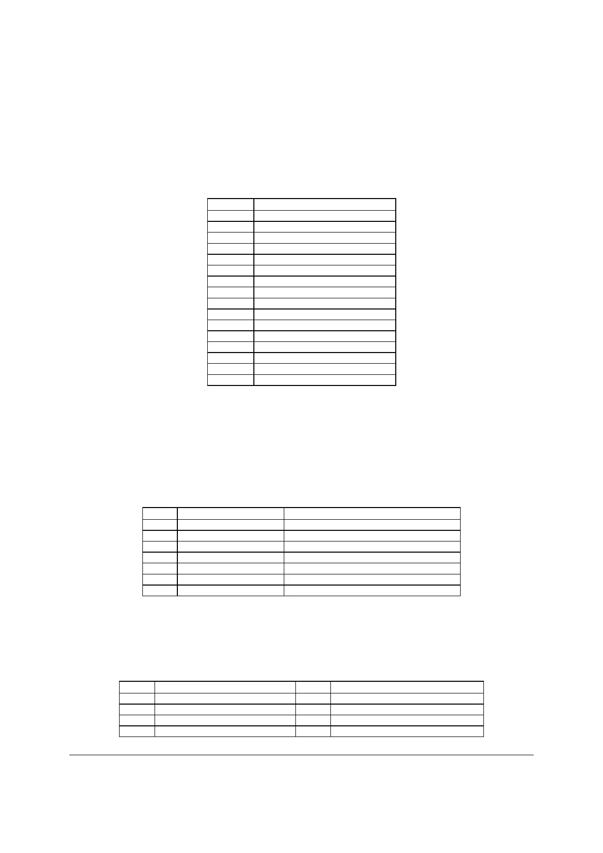
Table 57. RJ-45 10/100/1000 NIC Connector Pin-out (J5A1, J6A1)
Pin Signal Name
1 GND
2 P1V8_NIC
3 NIC_A_MDI3P
4 NIC_A_MDI3N
5 NIC_A_MDI2P
6 NIC_A_MDI2N
7 NIC_A_MDI1P
8 NIC_A_MDI1N
9 NIC_A_MDI0P
10 NIC_A_MDI0N
11 NIC_LINKA_1000_N (LED
12 NIC_LINKA_100_N (LED)
13 NIC_ACT_LED_N
14 NIC_LINK_LED_N
15 GND
16 GND
6.5.3 SATA Connectors
The server boards provide up to six SATA connectors: SATA-0 (J1G5), SATA-1 (J1G4), SATA-
2 (J1G1), SATA-3 (J1F4), SATA-4 (J1F1), and SATA-5 (J1E3).
The pin configuration for each connector is identical and defined in the following table:
Table 58. SATA/SAS Connector Pin-out (J1E3, J1G1, J1G4, J1G5, J1F1, J1F4)
Pin Signal Name
Description
1 GND Ground
2 SATA TX_P_C Positive side of transmit differential pair
3 SATA TX_N_C Negative side of transmit differential pair
4 GND Ground
5 SATA _RX_N_C Negative side of receive differential pair
6 SATA _RX_P_C Positive side of receive differential pair
7 GND Ground
6.5.4 SAS Module Slot
The server boards provide one SAS module slot (J2J1) to support the Intel
®
SAS Entry RAID
Module AXX4SASMOD card. The following table defines the pin-out:
Table 59. SAS Module Slot Pin-out (J2J1)
Pin Name Pin
Name
1 P3V3_AUX 2 RST_LPC_SAS_N
3 SW_RAID_MODE 4 GND
5 PE_ICH10_SAS_SW_C_TP0 6 PE_ICH10_SAS_SW_C_TN0
7 GND 8 GND

 Loading...


