Intel® Server Boards S5520HC, S5500HCV, and S5520HCT TPS Intel® Light Guided Diagnostics
Revision 1.8
Intel order number E39529-013
127
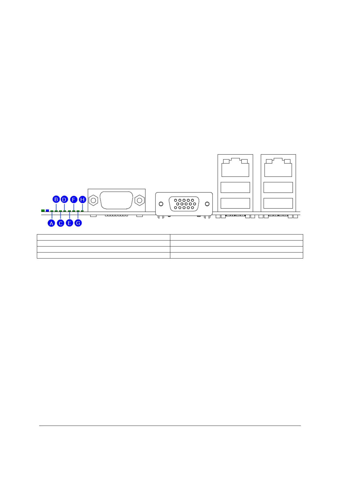
8.5 Post Code Diagnostic LEDs
Eight amber POST code diagnostic LEDs are located on the back edge of the server boards in
the rear I/O area of the server boards by the serial A connector.
During the system boot process, the BIOS executes a number of platform configuration
processes, each of which is assigned a specific hex POST code number. As each configuration
routine is started, the BIOS displays the given POST code to the POST code diagnostic LED’s
on the back edge of the server boards. To assist in troubleshooting a system hang during the
POST process, you can use the diagnostic LEDs to identify the last POST process executed.
See Appendix E for a complete description of how these LEDs are read and a list of all
supported POST codes.
A. Diagnostic LED #7 (MSB LED) E. Diagnostic LED #3
B. Diagnostic LED #6 F. Diagnostic LED #2
C. Diagnostic LED #5 G. Diagnostic LED #1
D. Diagnostic LED #4 H. Diagnostic LED #0 (LSB LED)
Figure 58. POST Code Diagnostic LED Locations

 Loading...


