Intel® Server Boards S5520HC, S5500HCV, and S5520HCT TPS Connector/Header Locations and Pin-outs
Revision 1.8
Intel order number E39529-013
115
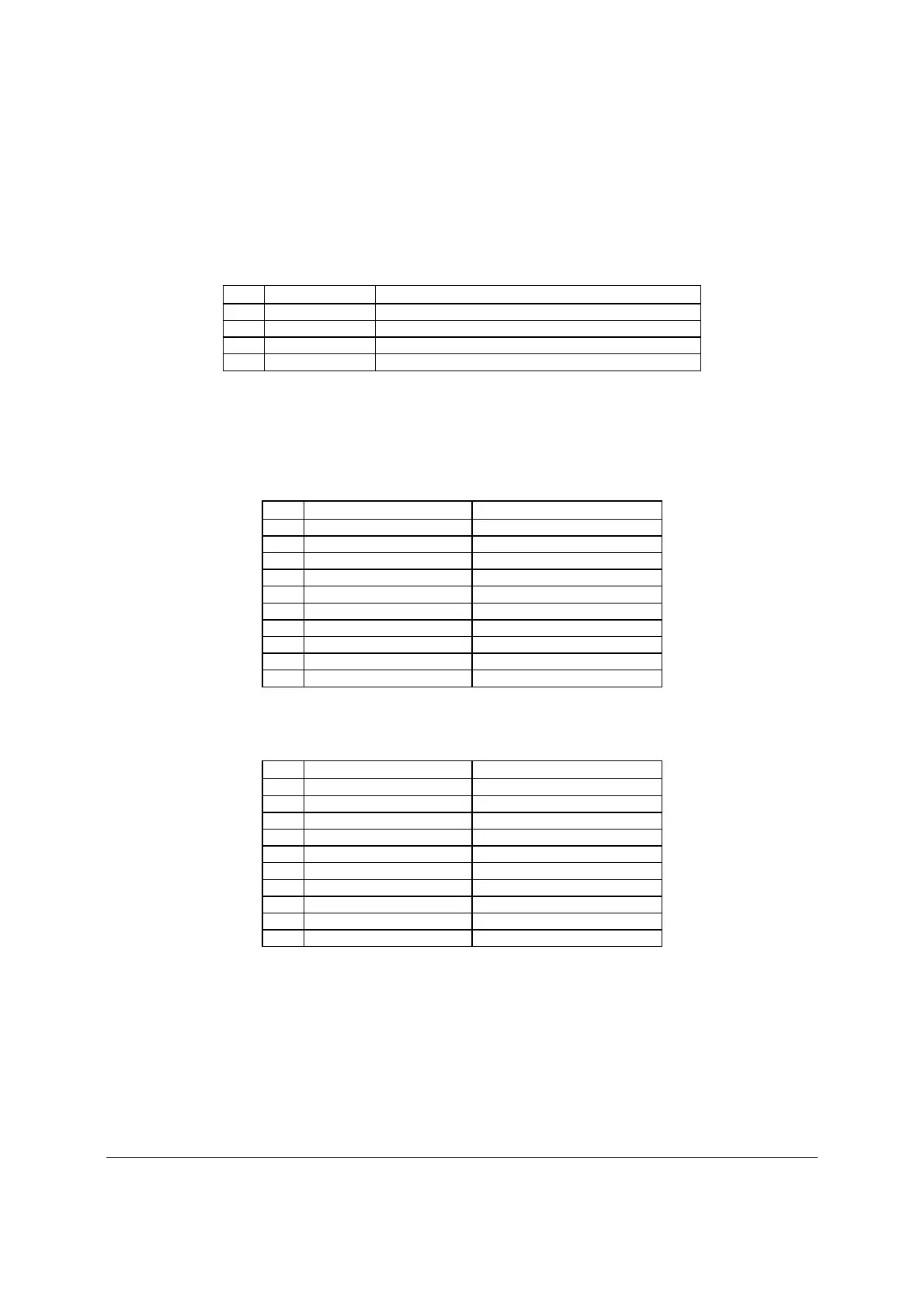
6.5.6 USB Connector
The following table details the pin-out of the external USB connectors (J5A1, J6A1) found on the
back edge of the server boards.
Table 62. External USB Connector Pin-out (J5A1, J6A1)
Pin Signal Name Description
1 USB_OC_5VSB USB_PWR
2 USB_PN DATAL0 (Differential data line paired with DATAH0)
3 USB_PP DATAH0 (Differential data line paired with DATAL0)
4 GND Ground
Two 2x5 connectors on the server boards (J1D1, J1D2) provide support for four additional USB
ports. J1D2 is recommended for front panel USB ports.
Table 63. Internal USB Connector Pin-out (J1D1)
Pin Signal Name
Description
1 USB_PWR45_5V USB power (port 4)
2 USB_PWR45_5V USB power (port 5)
3 USB_ICH_P4N_CONN USB port 4 negative signal
4 USB_ICH_P5N_CONN USB port 5 negative signal
5 USB_ICH_P4P_CONN USB port 4 positive signal
6 USB_ICH_P5P_CONN USB port 5 positive signal
7 Ground
8 Ground
9 Key No pin
10 TP_USB_ICH_NC Test point
Table 64. Internal USB Connector Pin-out (J1D2)
Pin Signal Name Description
1 USB_PWR68_5VSB USB power (port 6)
2 USB_PWR68_5VSB USB power (port 8)
3 USB_ICH_P6N_CONN USB port 6 negative signal
4 USB_ICH_P8N_CONN USB port 8 negative signal
5 USB_ICH_P6P_CONN USB port 6 positive signal
6 USB_ICH_P8P_CONN USB port 8 positive signal
7 Ground
8 Ground
9 Key No pin
10 TP_USB_ICH_NC Test point
One low-profile 2x5 connector (J2D2) on the server boards provides an option to support a low-
profile USB Solid State Drive.

 Loading...


