Intel® Server Boards S5520HC, S5500HCV, and S5520HCT TPS Connector/Header Locations and Pin-outs
Revision 1.8
Intel order number E39529-013
111
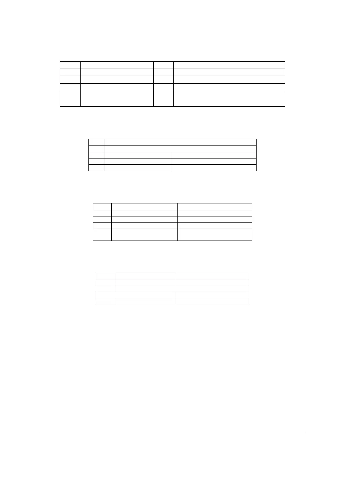
Pin Signal Name Pin
Signal Name
27 3V3_AUX 28 SPI_DO
29 GND 30 SPI_CLK
31 GND 32 SPI_DI
33
GND
34
RMM3_Present_N (pulled high on baseboard
and shorted to ground on the plug-in module)
6.3.2 LCP/IPMB Header
Table 52. LCP/IPMB Header Pin-out (J1G6)
Pin Signal Name
Description
1 SMB_IPMB_5VSB_DAT BMC IMB 5 V standby data line
2 GND Ground
3 SMB_IPMB_5VSB_CLK BMC IMB 5 V standby clock line
4 P5V_STBY +5 V standby power
6.3.3 HSBP Header
Table 53. HSBP Header Pin-out (J1F5, J1G3)
Pin
Signal Name
Description
1 SMB_IPMB_5V_DAT BMC IMB 5 V Data Line
2 GND Ground
3 SMB_IPMB_5V_CLK BMC IMB 5V Clock Line
4
P5V – HSBP_A
GND – HSBP_B
+5 V for HSBP A
Ground for HSBP B
6.3.4 SGPIO Header
Table 54. SGPIO Header Pin-out (J1G2)
Pin Signal Name
Description
1 SGPIO_CLOCK SGPIO Clock Signal
2 SGPIO_LOAD SGPIO Load Signal
3 SGPIO_DATAOUT0 SGPIO Data Out
4 SGPIO_DATAOUT1 SGPIO Data In
6.4 Front Panel Connector
The server boards provide a 24-pin SSI front panel connector (J1B3) for use with Intel
®
and
third-party chassis. The following table provides the pin-out for this connector:

 Loading...


