Connector/Header Locations and Pin-outs Intel® Server Boards S5520HC, S5500HCV, and S5520HCT TPS
Revision 1.8
Intel order number E39529-013
116
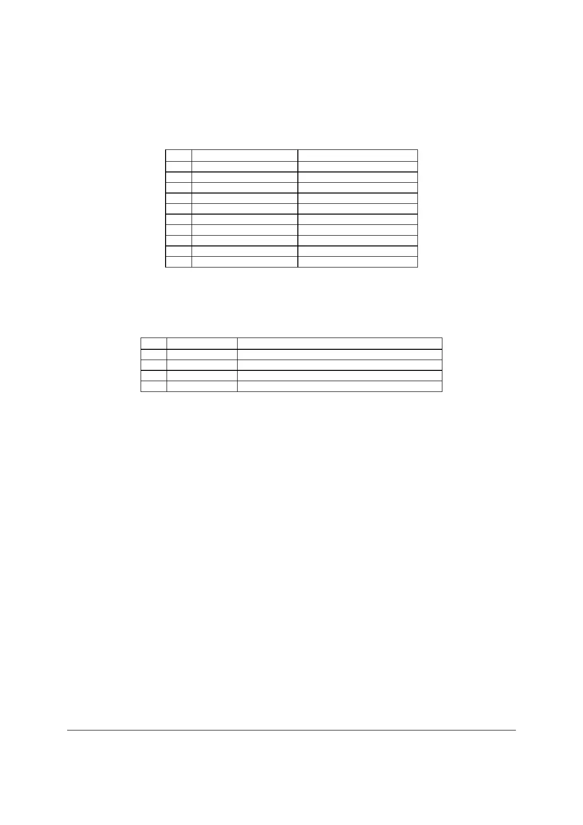
Table 65. Pin-out of Internal Low-Profile USB Connector for Solid State Drive (J2D2)
Pin Signal Name
Description
1 USB_PWR11_5V USB power
2 NC Not Connected
3 USB Data - USB port 11 negative signal
4 NC Not Connected
5 USB Data + USB port 11 positive signal
6 NC Not Connected
7 Ground Ground
8 NC Not Connected
9 Key No pin
10 LED# Activity LED
The server boards provide one additional Type A USB port (J1H2) to support the installation of
a USB device inside the server chassis.
Table 66. Internal Type A USB Port Pin-out (J1H2)
Pin Signal Name Description
1 USB_PWR7_5V USB_PWR
2 USB_ICH_P7N USB port 7 negative signal
3 USB_ICH_P7P USB port 7 positive signal
4 GND Ground
6.6 Fan Headers
The server boards provide three SSI-compliant 4-pin and four SSI-compliant 6-pin fan headers
to use as CPU and I/O cooling fans. 3-pin fans are supported on all fan headers. 6-pin fans are
supported on headers J1K1, J1K2, J1K4, and J1K5. 4-pin fans are supported on headers J1K1,
J1K2, J1K4, J1K5, J7K1, J9A2, and J9A3. The pin configuration for each of the 4-pin and 6-pin
fan headers is identical and defined in the following tables.
• Two 4-pin fan headers are designated as processor cooling fans:
- CPU1 fan (J9A2)
- CPU2 fan (J7K1)
• Four 6-pin fan headers are designated as hot-swap system fans:
- Hot-swap system fan 1 (J1K1)
- Hot-swap system fan 2 (J1K4)
- Hot-swap system fan 3 (J1K2)
- Hot-swap system fan 4 (J1K5)
• One 4-pin fan header is designated as a rear system fan:
- System fan 5 (J9A3)

 Loading...


