FRONT AXLE
B1220, B1620, B1820, WSM
6-S6
(EU)
(2) Disassembling Front Axle
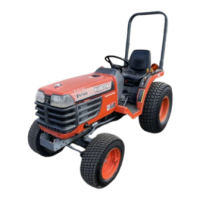
Tie-rod and Axle Bracket
1. Remove the slotted nut and remove the tie-rod (3).
2. Remove the front axle brackets (1), (2).
(When reassembling)
• Apply grease to the O-ring (4), (5), (6).
• After tightening the slotted nut (7) to the specified torque, install
the cotter pin as shown in the figure.
9Y1210272FAS0008US0
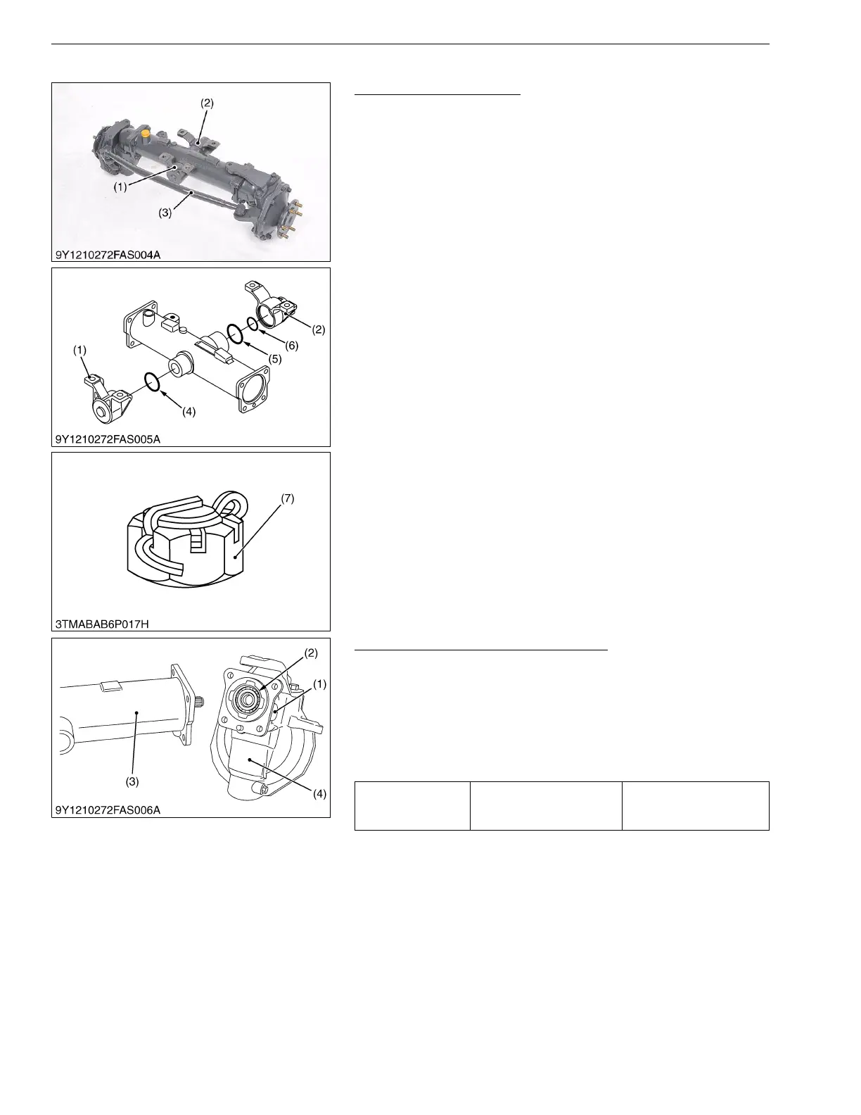
Bevel Gear Case and Front Gear Case
1. Remove the bevel gear case mounting screws.
2. Remove the bevel gear case (1) and front gear case (4) as a unit
from the front axle case (3).
(When reassembling)
• Apply grease to the O-ring (2) and take care not to damage it.
• Do not interchange right and left bevel gear case assemblies
and right and left gear case assemblies.
9Y1210272FAS0010US0
(1) Front Axle Bracket (Front)
(2) Front Axle Bracket (Rear)
(3) Tie-rod
(4) O-ring
(5) O-ring
(6) O-ring
(7) Slotted Nut
Tightening torque
Bevel gear case mounting
screw
78 to 90 N·m
7.9 to 9.2 kgf·m
58 to 66 lbf·ft
(1) Bevel Gear Case
(2) O-ring
(3) Front Axle Case
(4) Front Gear Case

 Loading...