ELECTRICAL SYSTEM
B1220, B1620, B1820, WSM
9-M8
(EU)
[2] B1620 AND B1820
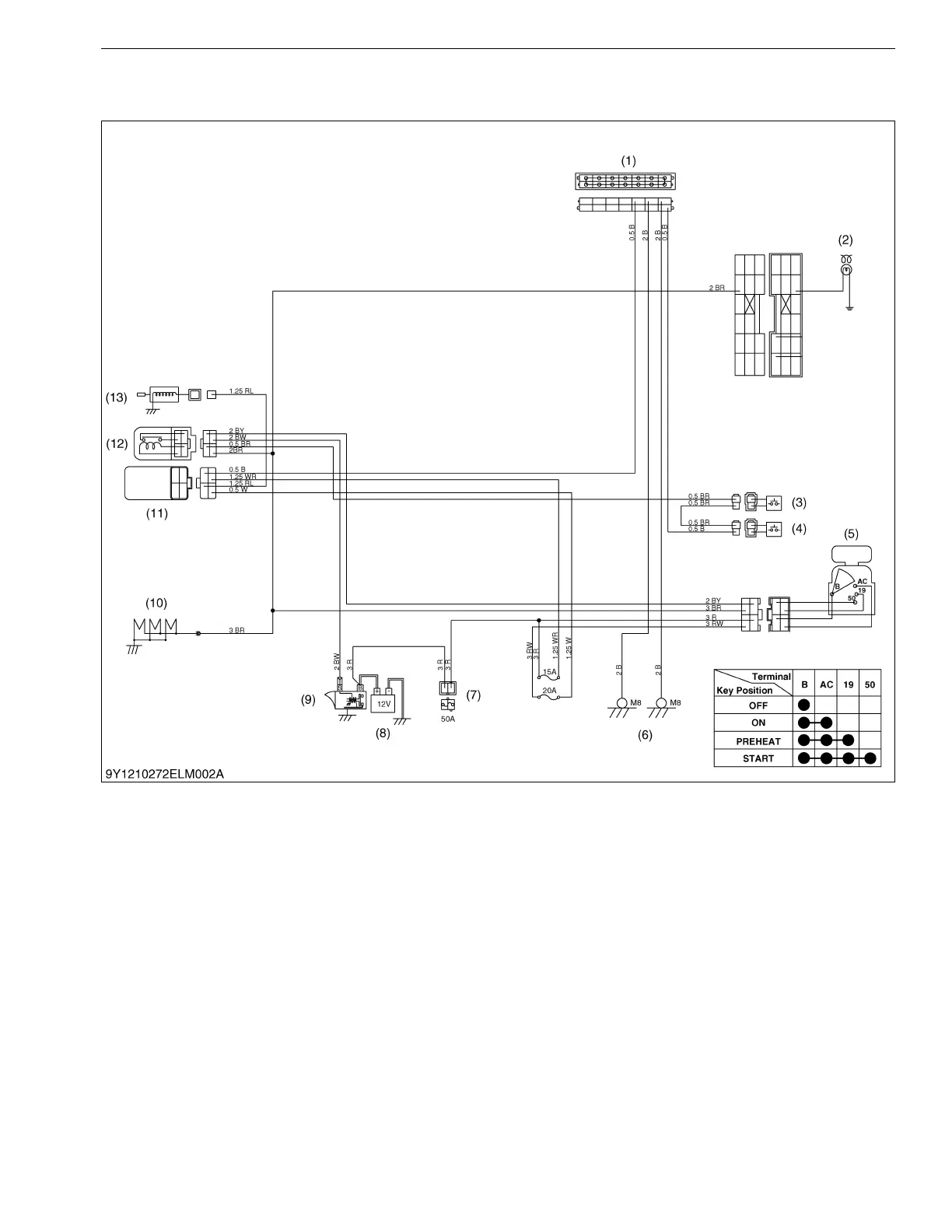
(1) Without OPC Type
When the main switch is turned to the PREHEAT position, the terminal B is connected to the terminals 19 and
AC. The glow plugs become red-hot, and at the same time, the glow plug indicator also lights on.
When the main switch is then turned to the START position with the safety switches on, the terminal B is
connected to the terminal 50 and AC. Consequently, battery current flows to the starter motor and start the engine.
The main switch automatically returns to the ON position, the terminal B is connected only to the terminal AC,
thereby causing the starting circuit to be opened, stopping the starter motor.
When the main switch turned from the ON position to the OFF position, the fuel cut-off solenoid moves the fuel
injection pump control rack to the "No Fuel Injection" position and stop the engine.
9Y1210272ELM0004US0
(1) Joint Connector
(2) Glow Plug Indication
(3) Safety Switch 1
(4) Safety Switch 2
(5) Main Switch
(6) Frame Earth
(7) Slow Blow Fuse
(8) Battery
(9) Starter
(10) Glow Plug
(11) Timer Relay
(12) Safety Relay
(13) Key Stop Solenoid

 Loading...