HYDRAULIC SYSTEM
B1220, B1620, B1820, WSM
8-S15
(EU)
[4] SERVICING
(1) Hydraulic Pump
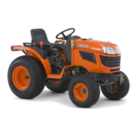
Clearance between Tip of Gear Tooth and Casing
1. Measure the clearance between gear and casing at several
points with feeler gauge.
2. If the clearance exceeds the allowable limit, replace the
assembly.
9Y1210272HYS0024US0
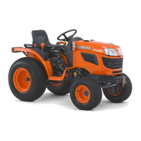
Clearance between Bushing and Gear Shaft
1. Measure the gear shaft O.D. with an outside micrometer.
2. Measure the bushing I.D. with a cylinder gauge.
3. If the clearance exceeds the allowable limit, replace it.
[B1220]
[B1620 and B1820]
9Y1210272HYS0025US0
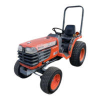
Side Plate Thickness
1. Measure the side plate thickness with an outside micrometer.
2. If the thickness is less than the allowable limit, replace it.
[B1220]
[B1620 and B1820]
9Y1210272HYS0026US0
Clearance between tip of
gear tooth and casing
Allowable limit
0.15 mm
0.059 in.
Clearance between
busing and shaft
Factory specification
0.0050 to 0.088 mm
0.00020 to 0.0034 in.
Allowable limit
0.12 mm
0.0047 in.
Bushing I.D. Factory specification
12.000 to 12.068 mm
0.47244 to 0.47511 in.
Clearance between
busing and shaft
Factory specification
0.020 to 0.091 mm
0.00079 to 0.0035 in.
Allowable limit
0.12 mm
0.0047 in.
Bushing I.D. Factory specification
15.000 to 15.061 mm
0.59056 to 0.59295 in.
Side plate thickness
Factory specification
1.98 to 2.00 mm
0.0780 to 0.0787 in.
Allowable limit
1.9 mm
0.075 in.
Side plate thickness
Factory specification
2.48 to 2.50 mm
0.0977 to 0.0984 in.
Allowable limit
2.40 mm
0.0945 in.
 Loading...