ELECTRICAL SYSTEM
B1220, B1620, B1820, WSM
9-S30
(EU)
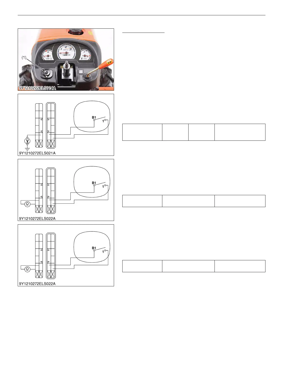
(15) Head Light Switch [B1220]
Head Light Switch
1. Remove the steering wheel and steering boot.
2. Disconnect the head light switch connector.
3. Remove the head light switch (1) and perform the following 1) to
3).
1) Connector Voltage
1. Measure the voltage with a voltmeter across the connector B1
terminal and chassis when the main switch is "ON" position.
2. If the voltage differs from the battery voltage, the wiring harness
and main switch is faulty.
2) Head Light Switch Continuity When Setting Switch at OFF
Position
1. Set the light switch to the OFF position.
2. Measure the resistance with an ohmmeter across the B1
terminal to the terminal 1.
3. If infinity is not indicated, the head light switch is faulty.
3) Head Light Switch Continuity When Setting Switch at On
Position
1. Set the light switch to the ON position.
2. Measure the resistance with an ohmmeter across the B1
terminal to the terminal 1.
3. If 0 Ω is not indicated, the head light switch is faulty.
9Y1210272ELS0028US0
(1) Head Light Switch
Voltage
Main switch
at "ON"
position
B1 terminal
– Chassis
Battery voltage
Resistance (Switch
at OFF position)
B1 terminal – 1 terminal Infinity
Resistance (Switch
at ON position)
B1 terminal – 1 terminal 0 Ω

 Loading...