HYDRAULIC SYSTEM
B1220, B1620, B1820, WSM
8-S13
(EU)
(3) Hydraulic Cylinder
Control Valve
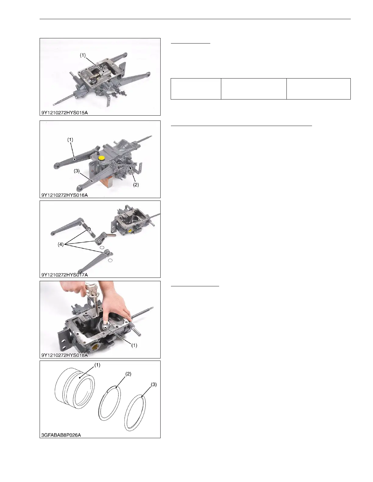
1. Remove the control valve mounting screws, and remove the
control valve (1).
(When reassembling)
• Take care not to damage the O-rings.
9Y1210272HYS0018US0
Lift Arm, Hydraulic Arm Shaft and Hydraulic Arm
1. Remove the feedback rod lock nuts and spring.
2. Remove the lift arm, L.H. (1).
3. Remove the hydraulic arm shaft and lift arm, R.H. (3) as a unit.
(When reassembling)
• Align the alignment marks (4) of the hydraulic arm and hydraulic
arm shaft.
• Align the alignment marks (4) of the lift arm, L.H. and hydraulic
arm shaft.
• Apply grease to the right and left bushings and O-rings.
• Take care not to damage the O-rings.
9Y1210272HYS0019US0
Hydraulic Piston
1. Inject the compressed air into the hydraulic cylinder, and take
out the hydraulic piston (1).
(When reassembling)
• Take care not to damage the O-ring (3) and backup ring (2).
• Apply transmission fluid to the O-ring.
• Replace the O-ring if it is defective, worn or scratched, and it
cause the oil leakage.
9Y1210272HYS0020US0
Tightening torque
Control valve mounting
screw
24 to 27 N·m
2.4 to 2.8 kgf·m
18 to 20 lbf·ft
(1) Control Valve
(1) Lift Arm, L.H.
(2) Feedback Rod
(3) Lift Arm, R.H.
(4) Alignment Mark
(1) Hydraulic Piston
(2) Backup Ring
(3) O-ring