ELECTRICAL SYSTEM
B1220, B1620, B1820, WSM
9-S14
(EU)
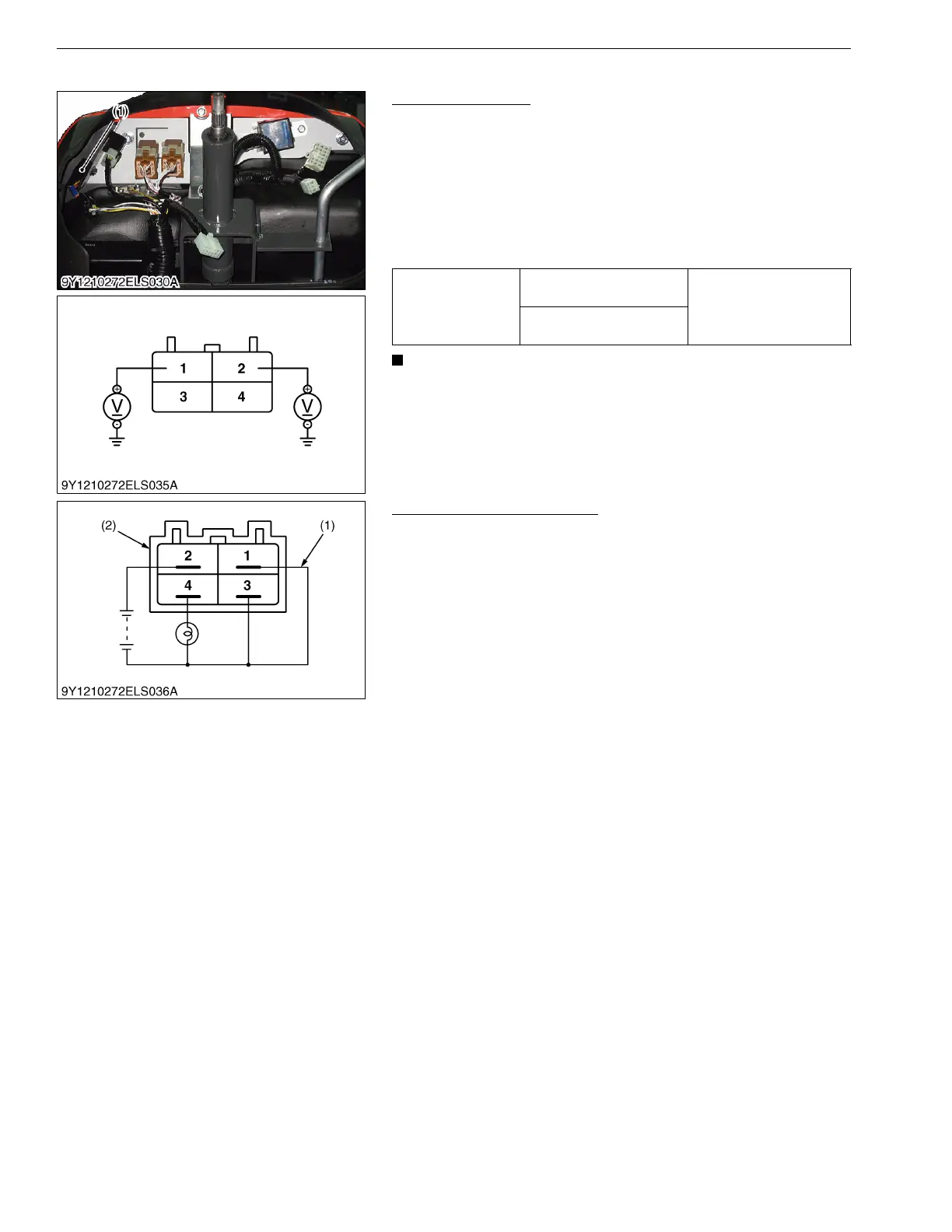
(5) Timer Relay 2 (With OPC Type)
Connector Voltage
1. Disconnect the connector from the timer relay 2 after turning the
main switch off.
2. Measure the voltage with a voltmeter across the connector 1
terminal and chassis.
3. Measure the voltage with a voltmeter across the connector 2
terminal and chassis.
4. If these voltage differ from the battery voltage, the wiring
harness or main switch is faulty.
• The timer relay 2 shall be installed with a part of connector
dawn ward.
If the timer relay 2 is mounted up-side-down or inclined
side ways, water may intrude timer solenoid failure.
9Y1210272ELS0077US0
Timer Relay 2 Actuator Test
1. Connect a jumper lead from the terminal 1 and terminal 2 to the
battery positive terminal.
2. Connect a jumper lead from the terminal 3 to battery negative
terminal.
3. Connect a jumper lead from the terminal 4 to a lamp.
4. The lamp lights when disconnect the jumper lead from the
terminal. Confirm the lamp goes out at approx. 1 seconds later
after the lamp lights.
5. If the lamp does not go out at approx. 1 seconds, timer relay is
faulty.
9Y1210272ELS0078US0
Voltage
Connector 1 terminal –
Chassis
Approx. battery voltage
Connector 2 terminal –
Chassis
(1) Timer Relay 2
(1) Jumper Lead (2) Timer Relay 2

 Loading...