ELECTRICAL SYSTEM
B1220, B1620, B1820, WSM
9-S39
(EU)
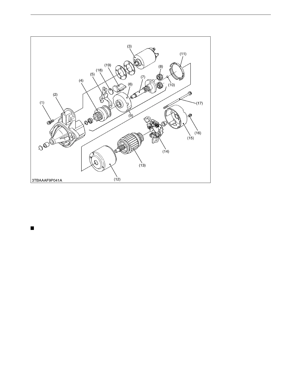
[2] DISASSEMBLING AND ASSEMBLING
(1) Starter
1. Disconnect the connecting lead from the magnetic switch (3).
2. Remove the screw (1) and remove the magnet switch (3).
3. Remove the screw (16) and through bolt (17), and separate the rear end frame (15).
4. Remove the brush holder (14).
5. Draw out the armature (13) and yoke (12).
6. Remove the gasket (11), gasket (19) and plate (18).
7. Draw out the shaft assembly (9) with the drive lever (5).
• Do not damage the brush and commutator.
• Do not miss the ball (10).
9Y1210272ELS0046US0
(1) Screw
(2) Front Bracket
(3) Magnetic Switch
(4) Overrunning Clutch
(5) Drive Lever
(6) Internal Gear
(7) Shaft
(8) Planetary Gear
(9) Shaft Assembly
(10) Ball
(11) Gasket
(12) Yoke
(13) Armature
(14) Brush Holder
(15) Rear End Frame
(16) Screw
(17) Through Bolt
(18) Plate
(19) Gasket

 Loading...