Home
Kubota
Tractor
B1620
Kubota B1620 Workshop Manual
4
of 1
of 1 rating
343 pages
Give review
Manual
Specs
To Next Page
To Next Page
To Previous Page
To Previous Page
Loading...
INFORMATION
B1220, B1620, B1820, WSM
I-4
(EU)
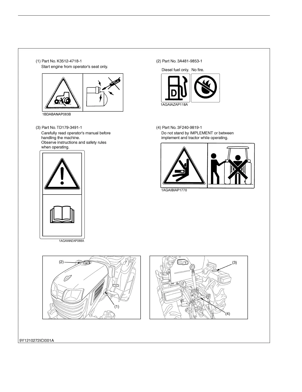
2. SAFETY
DECALS
The following safety decals (
pictorial safety labels) ar
e installed on the machine. If a d
ecal becomes
damaged, illegible or is not on the machine, replace
it. The decal pa
rt number is
listed in the parts list.
WSM000001INI0014US0
9Y1210272INI0001US0
KiSC issued 07, 2011 A
7
9
Table of Contents
Information
4
Table of Contents
4
Safety First
5
Safety Decals
5
Safety Decals
8
Specifications
10
Traveling Speeds
11
Dimensions
12
General
14
1 Tractor Identification
15
Model Name and Serial Number
15
Cylinder Number
16
2 General Precautions
17
3 Handling Precautions for Electrical Parts and Wiring
18
Wiring
18
Battery
20
Fuse
20
Connector
20
Handling of Circuit Tester
21
Color of Wiring
22
4 Lubricants, Fuel and Coolant
23
5 Tightening Torques
25
General Use Screws, Bolts and Nuts
25
Stud Bolts
25
Metric Screws, Bolts and Nuts
26
American Standard Screws, Bolts and Nuts with Unc or Unf Threads
26
Plugs
26
6 Maintenance Check List
27
7 Check and Maintenance
31
Daily Check
31
Check Points of Initial 50 Hours
32
Check Points of Every 50 Hours
34
Check Points of Every 100 Hours
37
Check Points of Every 200 Hours
43
Check Points of Every 400 Hours
44
Check Point of Every 800 Hours
46
Check Point of Every 1500 Hours
46
Check Point of Every 3000 Hours
46
Check Point of 1 Year
46
Check Points of 2 Years
47
Others
50
8 Special Tools
53
Special Tools for Engine
53
Special Tools for Tractor
58
9 Tires
63
Tire Pressure
63
Tread Adjustment
64
Front Wheels
64
Rear Wheels
65
Tire Liquid Injection
66
Servicing
69
Troubleshooting
70
Servicing Specifications
73
Tightening Torques
78
Checking, Disassembling and Servicing
79
Checking and Adjusting
79
Engine Body
79
Lubricating System
81
Cooling System
82
Fuel System
84
Preparation
88
Separating Engine from Tractor
88
Disassembling and Assembling
95
Cylinder Head, Valves and Oil Pan
95
Gear Case and Timing Gears
100
Piston and Connecting Rod
103
Flywheel and Crankshaft
105
Servicing
108
Cylinder Head and Valves
108
Timing Gears
114
Piston and Connecting Rod
117
Crankshaft
119
Cylinder
124
Oil Pump
125
Servicing
129
Troubleshooting
130
Servicing Specifications
131
Tightening Torques
132
Checking, Disassembling and Servicing
133
Checking and Adjusting
133
Preparation
133
Separating Engine from Clutch Housing
133
Separating Clutch Assembly
139
Servicing
140
Mechanism
142
1 Structure
143
B1220
145
B1620 and B1820
145
2 Power Train for Travelling System
145
Main Gear Shift Section
145
Hi-Lo Gear Shift Section
146
3 Power Train for Pto Gear
147
Rear Pto Shift Section
147
B1220
147
B1620 and B1820
148
MID Pto Shift Section [If Equipped]
149
B1620 and B1820
149
4 Shift Linkage
150
Servicing
151
Troubleshooting
152
Servicing Specifications
153
Tightening Torques
154
Disassembling and Servicing
155
Preparation
155
Separating Engine from Clutch Housing
155
Separating Center Frame and Transmission
162
Disassembling and Assembling
165
Disassembling Clutch Housing
165
Disassembling Transmission Case
166
Disassembling Differential Gear Case
171
Servicing
172
Clutch Housing
172
Transmission Case
172
Differential Gear
174
Rear Axle
177
Servicing
180
1 Troubleshooting
181
2 Tightening Torques
182
3 Disassembling and Servicing
183
Disassembling and Assembling
183
Servicing
185
Mechanism
187
1 Linkage
188
B1220
188
B1620 and B1820
189
2 Operation
190
Servicing
191
Troubleshooting
192
Servicing Specifications
193
Tightening Torques
194
Checking, Disassembling and Servicing
195
Checking and Adjusting
195
Disassembling and Assembling
196
Brake Pedal [B1220]
196
Brake Pedal [B1620 and B1820]
197
Separating Rear Axle Case
198
Disassembling Rear Axle Case
201
Servicing
202
Front Axle
203
Servicing
206
Troubleshooting
207
Servicing Specification
208
Tightening Torques
209
Checking, Disassembling and Servicing
210
Disassembling and Assembling
210
Separating Front Axle
210
Disassembling Front Axle
212
Servicing
216
Servicing
222
Troubleshooting
223
Servicing Specifications
225
Tightening Torques
227
Checking, Disassembling and Servicing
228
Checking and Adjusting
228
Manual Steering Model
228
Power Steering Model
229
Hydraulic Pump for Power Steering
231
Preparation
232
Hydraulic Pump for Power Steering [Only B1820]
232
Separating Manual Steering Controller Box Assembly
233
Disassembling and Assembling
236
Hydraulic Pump for Power Steering [Only B1820]
236
Manual Steering Controller Body [If Equipped]
237
Power Steering Controller Body [Only B1820]
239
Servicing
241
Hydraulic Pump for Power Steering
241
Manual Steering Controller Body [If Equipped]
242
Power Steering Controller Body [Only B1820]
243
Hydraulic System
244
Mechanism
245
1 Hydraulic Circuit
246
B1220
246
B1620 and B1820 (Manual Steering Model)
247
B1820 (Power Steering Model)
248
2 Oil Flow
249
B1220
249
B1620 and B1820 (Manual Steering Model)
249
B1820 (Power Steering Model)
250
3 Hydraulic Pump
251
Manual Steering Model
251
Power Steering Model
251
Hydraulic Control Valve
252
Feedback Linkage for Position Control
253
Relief Valve
254
Hydraulic Cylinder
255
Hydraulic Block Type Outlet
256
Rear Hydraulic Outlet
256
Servicing
257
2 Servicing Specifications
259
4 Checking, Disassembling and Servicing
262
Checking and Adjusting
262
Hydraulic Pump for 3 Point Hydraulic System
262
Relief Valve
264
Lift Arm
265
Preparation
266
Hydraulic Pump
266
Hydraulic Cylinder and Control Valve
266
Disassembling and Assembling
268
Hydraulic Pump [Manual Steering Model]
268
Hydraulic Pump [Power Steering Model]
269
Hydraulic Cylinder
270
Hydraulic Control Valve
271
Servicing
272
Hydraulic Pump
272
Hydraulic Cylinder
273
Electrical System
274
Mechanism
275
1 Wiring Diagram
276
B1220 (Without Opc Type)
276
B1220 (with Opc Type)
277
B1620 and B1820 (Without Opc Type)
278
B1620 and B1820 (with Opc Type)
279
B1620 and B1820 (with Opc and Pto Gear Shift Lever Switch Type)
280
2 Starting System
281
Without OPC Type
281
With OPC Type
282
B1620 and B1820
283
Without OPC Type
283
With OPC Type
284
With OPC and PTO Gear Shift Lever Switch Type
285
Safety Switch and Engine Condition
286
Related Switches
286
Engine Starting Conditions
286
Related Switches
287
Engine Starting Conditions and Automatic Engine Stop
290
3 Charging System
291
B1220
291
B1620 and B1820
292
4 Lighting System
293
B1220
293
Head Light
293
B1620 and B1820
294
Head Light
294
Turn Signal Light
294
Hazard Lamp
295
5 Easy Checker
296
Indication Items
296
Engine Oil Pressure Lamp
296
Servicing
297
Default Chapter
301
B1620 and B1820
301
2 Servicing Specifications
305
3 Checking, Disassembling and Servicing
306
Battery
306
Main Switch
308
Key Stop Solenoid
309
Key Stop Solenoid Relay
310
Timer Relay 2 (with OPC Type)
311
Relay (2M) (with OPC Type)
312
Glow Plug
313
Safety Switches
314
Starter
323
AC Dynamo [B1220]
323
Regulator [B1220] (Without OPC Type)
324
Regulator [B1220] (with OPC Type)
325
Alternator [B1620 and B1820]
326
Head Light Switch [B1220]
327
Combination Switch [B1620 and B1820]
328
Hazard Switch [B1620 and B1820]
330
Brake Switch [B1620 and B1820]
331
Flasher Unit [B1620 and B1820]
332
Easy Checker
333
Gauge
335
Disassembling and Assembling
336
Starter
336
AC Dynamo [B1220]
337
Alternator [B1620 and B1820]
337
Servicing
340
Starter
340
Alternator
341
Other manuals for Kubota B1620
Operator's Manual
91 pages
Assembly Instructions
19 pages
4
Based on 1 rating
Ask a question
Give review
Questions and Answers:
Need help?
Do you have a question about the Kubota B1620 and is the answer not in the manual?
Ask a question
Kubota B1620 Specifications
General
Engine Type
Diesel
Cylinders
3
Fuel Type
Diesel
Hydraulic System Type
Open center
Drive
4WD
3-Point Hitch Category
Category I
Related product manuals
Kubota B1220
343 pages
Kubota B1830
101 pages
Kubota B1700
233 pages
Kubota B1820
91 pages
Kubota WSM B1830
41 pages
Kubota WSM B1710
370 pages
Kubota BX24
128 pages
Kubota BX23S
178 pages
Kubota B2320
88 pages
Kubota B2601
94 pages
Kubota B2650
112 pages
Kubota B2301
94 pages

 Loading...