ELECTRICAL SYSTEM
B1220, B1620, B1820, WSM
9-S29
(EU)
(14) Alternator [B1620 and B1820]
Alternator
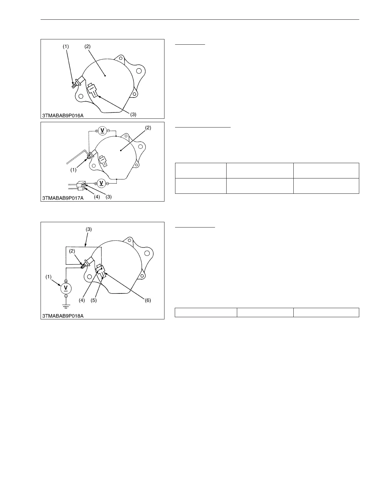
1. Disconnect the 2P connector (3) from alternator after turning the
main switch OFF.
2. Perform the following checkings.
9Y1210272ELS0025US0
Connector Voltage
1. Turn the main switch OFF. Measure the voltage between the B
terminal (1) and the chassis.
2. Turn the main switch ON. Measure the voltage between the IG
terminal (3) and the chassis.
9Y1210272ELS0026US0
No-Load Test
1. Connect the 2P connector (6) to previous positions of the
alternator after turning the main switch OFF.
2. Connect the jumper lead (3) between IG terminal (4) and B
terminal (2).
3. Start the engine and then set at idling speed.
4. Disconnect the negative cable from the battery.
5. Measure the voltage between the B terminal (2) and the
chassis.
6. If the measurement is less than the factory specifications,
disassemble the alternator and check the IC regulator.
(Reference)
• Once the engine has started, the alternator temperature rises
quickly up to an ambient temperature of 70 to 90 °C (158 to
194 °F). As the temperature goes higher than 50 °C (122 °F),
the alternator voltage slowly drops ; at higher than 100 °C
(212 °F), it drops by about 1 V.
WSM000001ELS0014US0
(1) B Terminal
(2) Alternator
(3) 2P Connector
Voltage (Main
switch at OFF)
B terminal – Chassis Approx. battery voltage
Voltage (Main
switch at ON)
IG terminal – Chassis Approx. battery voltage
(1) B Terminal
(2) Alternator
(3) IG Terminal
(4) L Terminal
Voltage Factory specification More than 14 V
(1) Voltmeter
(2) B Terminal
(3) Jumper Lead
(4) IG Terminal
(5) L Terminal
(6) 2P Connector

 Loading...