ELECTRICAL SYSTEM
B1220, B1620, B1820, WSM
9-S33
(EU)
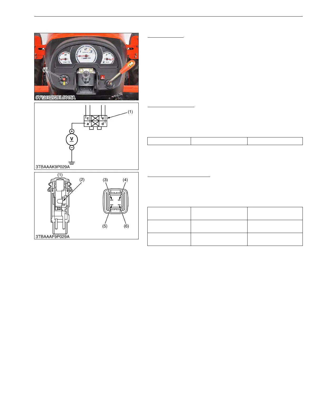
(17) Hazard Switch [B1620 and B1820]
Hazard Switch
1. Remove the steering wheel and steering boot.
2. Disconnect the 4P connector from hazard switch after
disconnect the battery negative cable.
3. Remove the hazard switch.
4. Perform the following checks.
9Y1210272ELS0030US0
Connector Voltage
1. Connect the battery negative cable, then measure the voltage
with a voltmeter across the a terminal and chassis.
2. If the voltage differ from the battery voltage, the wiring harness
is faulty.
9Y1210272ELS0031US0
Hazard Switch continuity
1. Measure the resistance with ohmmeter across the a terminal (3)
and c terminal (5), and across the d terminal (6) and e terminal.
2. If the measurement is not following below, the hazard switch (1)
or the bulb (2) are faulty.
9Y1210272ELS0032US0
(1) Hazard Switch
Voltage a terminal – Chassis Approx. battery voltage
(1) 4P Connector
Resistance
(Switch at OFF)
a terminal – c terminal Infinity
Resistance
(Switch at ON)
a terminal – c terminal 0 Ω
Resistance
(Bulb)
d terminal – e terminal Approx. 13 Ω
(1) Hazard Switch
(2) Bulb
(3) a Terminal
(4) b Terminal
(5) c Terminal
(6) d Terminal

 Loading...