90-826148R2 MARCH 1997 ELECTRICAL - 2D-17
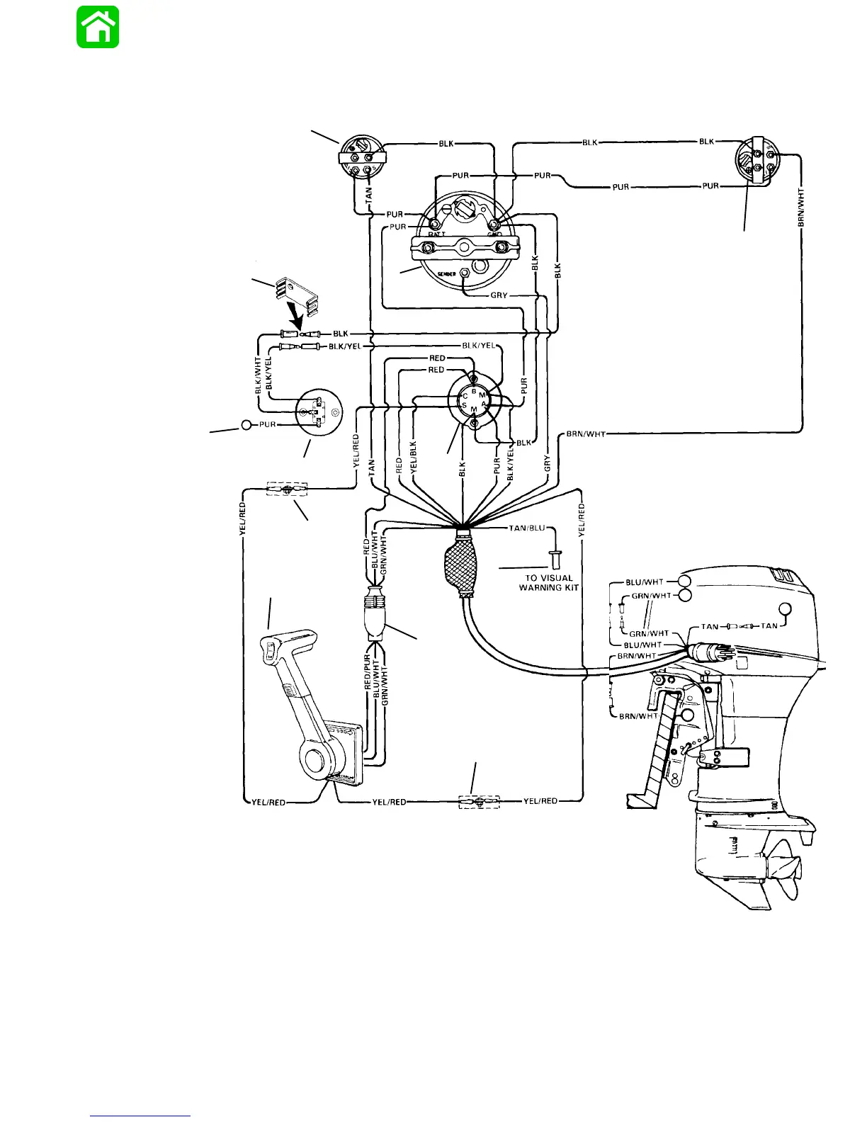
Instrument/Lanyard Stop
Switch Wiring Diagram
IMPORTANT: On installations where gauge
options will not be used, tape back any unused
wiring harness leads.
52715
BLK = Black
BLU = Blue
BRN = Brown
GRY = Gray
GRN = Green
ORN = Orange
PNK = Pink
PUR = Purple
RED = Red
TAN = Tan
WHT = White
YEL = Yellow
LIT = Light
DRK = Dark
a
b
c
d
e
f
h
i
j
k
j
a - Ignition/Choke Switch
b - Lanyard Stop Switch
c - Lead Not Used On Outboard Installations
d - Retainer
e - Tachometer
f - Trim Indicator Gauge (Optional)
g - Temperature Gauge
h - Remote Control
i - Power Trim Harness Connector
j - Connect Wires Together with Screw and Hex Nut (2
Places); Apply Quicksilver Liquid Neoprene to Connections
and Slide Rubber Sleeve over Each Connection
k - Lead to Optional Visual Warning Kit

 Loading...