90-826148R2 MARCH 1997 ELECTRICAL - 2A-23
Testing Ignition Components
Resistance Tests
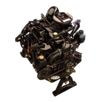
TIMING PROTECTION MODULE
Normally, if timing advances and retards with corre-
sponding changes in RPM, most likely the TPM is
functioning correctly. Refer to “Ignition Diagnostic
Procedures” preceding, for individual failure sce-
narios.
STATOR
A resistance check can be made on charge coils.
Ohmmeter should indicate as follows:
Black Stator between GREEN/WHITE and GREEN
leads (525-625 ohms)
Red Stator between GREEN/WHITE and WHITE/
GREEN leads (660-710 ohms).
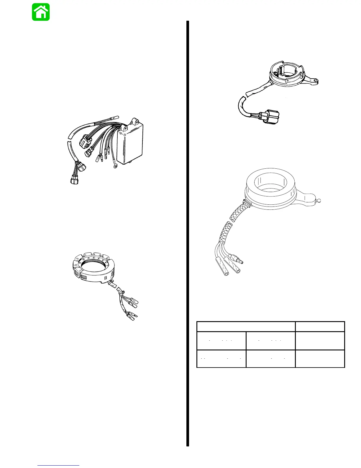
TRIGGER (S/N-0G589999 & BELOW)
A resistance check can be made on trigger coil be-
tween WHITE/BLACK and WHITE leads. Ohmmeter
should indicate between 1100 - 1300 ohms.
TRIGGER (S/N-0G590000 & ABOVE)
55767
A resistance test is not used on the trigger. Test trig-
ger as outlined under “Trigger Output Test”.
Trigger Output Test
20 DVA Scale
Positive Meter
Negative Meter
DVA Reading
Lead (+) Lead (–)
White Test
Black Test Har-
2 - 8 Volts
Harness Lead ness Lead
If reading is below specifications replace trigger. If
reading is above specifications check CDM.
NOTE: If voltage remains low after installing a new
trigger, replace CDM.

 Loading...