90-826148R2 MARCH 1997 ELECTRICAL - 2A-17
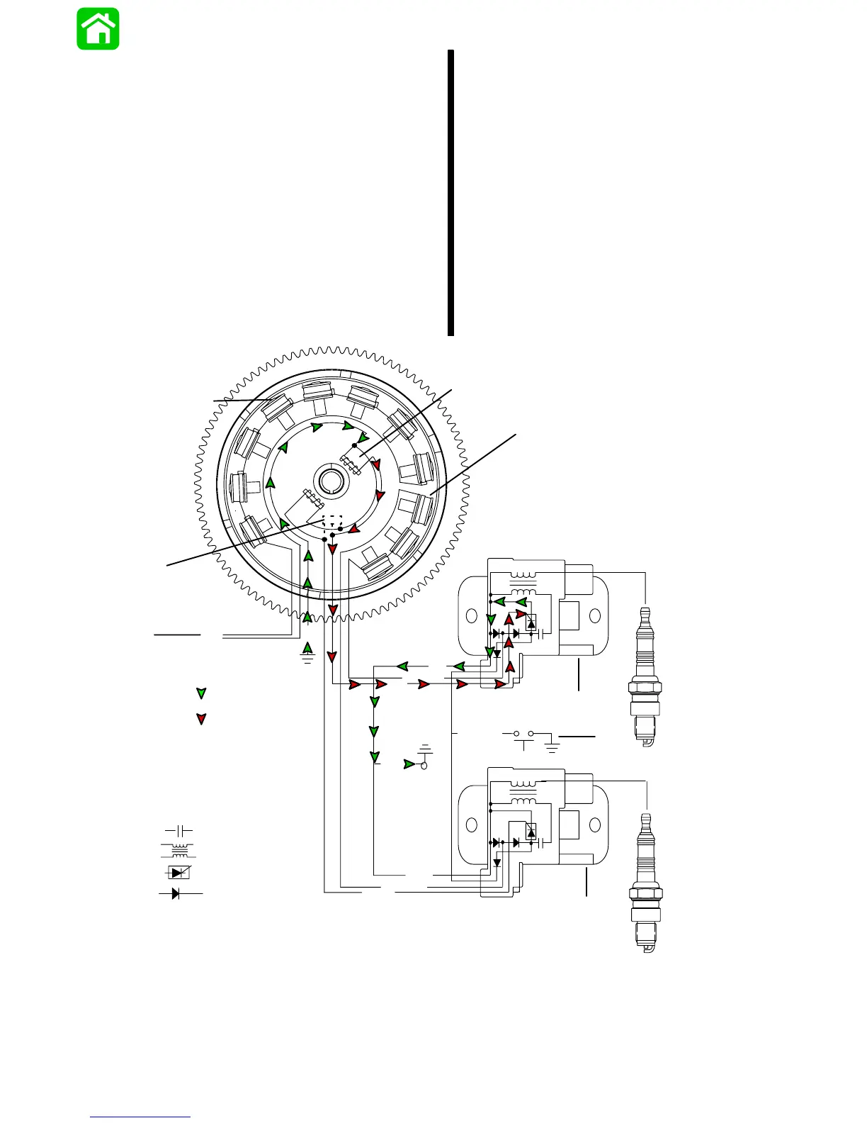
#1 Cylinder Trigger Circuit
The TRIGGER assembly (also mounted under
the flywheel) has one coil for each cylinder.
These coils are mounted adjacent to the fly-
wheel center hub. The center hub of the flywheel
contains a permanent magnet with one north–
south transitions. As the flywheel rotates, the
magnet north–south transitions pass the trigger
coils. This causes the trigger coils to produce a
voltage pulse which is sent to the respective ca-
pacitor discharge module (CDM).
A positive voltage pulse (N–S) will activate the
electronic switch (SCR) inside the capacitor dis-
charge module (CDM). The switch discharges
the capacitor voltage through the coil primary
windings. The return voltage pulse exits the
CDM through the ground wire and returns
through the trigger ground. Once inside the trig-
ger the voltage will supply the bias capacitor with
a negative charge. For the next trigger in se-
quence to activate its CDM (SCR), the positive
trigger voltage must first over come this offset
bias capacitor voltage. The delay produced by
having to over come this offset bias capacitor
voltage prevents the timing from electronically
advancing as engine speed increases.
N
S
S
S
S
S
S
N
N
N
N
N
SN
BLK
GRN/WHT
WHT/GRN
YEL
YEL
BLK
WHT
PPL
BLK/YEL
+
+
_
_
BLK
BLK
Return Voltage
Source Voltage
Capacitor-
Coil-
SCR-
Diode-
1
2
a
b
c
f
h
e
d
g
a - Battery Charging Coils
b - Trigger Coils
c - Capacitor Charge Coils
d - CDM #1
e - CDM #2
f - Rev. Limiter
g - Stop Switch
h - To Voltage Regulator
 Loading...