90-826148R2 MARCH 1997 ELECTRICAL - 2A-15
Theory of Operation
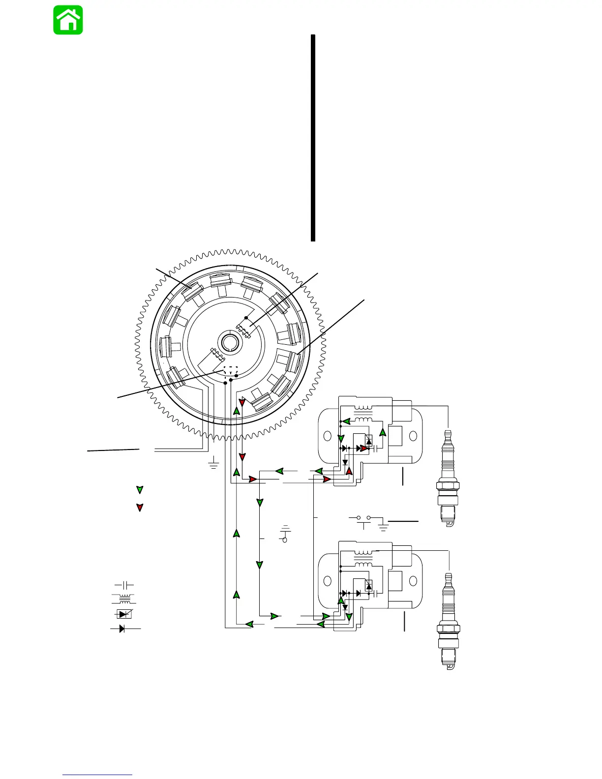
This outboard ignition system is alternator–driv-
en (distributor–less) capacitor discharge sys-
tem. Major components of the ignition system
are the flywheel, stator, trigger, capacitor dis-
charge modules (CDM’s) and spark plugs. Each
capacitor discharge module functions as a com-
bination switchbox and secondary ignition coil.
CAPACITOR CHARGING #1 CDM
The STATOR assembly is mounted to the block
below the flywheel and has 3 CAPACITOR
CHARGING COILS wound in series. The FLY-
WHEEL is fitted with 6 permanent magnets in-
side the outer rim. The flywheel rotates the per-
manent magnets past the capacitor charging
coils–causing the coils to produce AC voltage
(260–320 volts). The AC voltage is then con-
ducted to the CAPACITOR DISCHARGE MOD-
ULES (CDM), where it is rectified (DC) and
stored in a capacitor. The stator voltage return
path is through the ground wire of the other CDM
and back through that CDM’s charging coil wire
to the capacitor charging coils.
N
S
S
S
S
S
S
N
N
N
N
N
SN
BLK
GRN/WHT
WHT/GRN
YEL
YEL
BLK
WHT
PPL
BLK/YEL
+
+
_
_
BLK
BLK
Return Voltage
Source Voltage
Capacitor-
Coil-
SCR-
Diode-
1
2
a
b
c
d
f
g
h
e
a - Battery Charging Coils
b - Trigger Coils
c - Capacitor Charge Coils
d - CDM #1
e - CDM #2
f - Rev. Limiter
g - Stop Switch
h - To Voltage Regulator
 Loading...