90-826148R2 MARCH 1997 ATTACHMENTS/CONTROL LINKAGE - 7B-5
Adjustments
Tiller Handle Model with
Mechanical Spark Advance
(S/N-0G590000 & Above)
1. With engine off and gear shift in neutralposition,
loosen cam follower screw.
2. Backoffidlespeedscrewuntilthethrottleshutter
positioner does not touch the taper of idle speed
screw. (Throttle plate closed).
3. Loosen throttle cable jam nuts.
55896
a
b
c
d
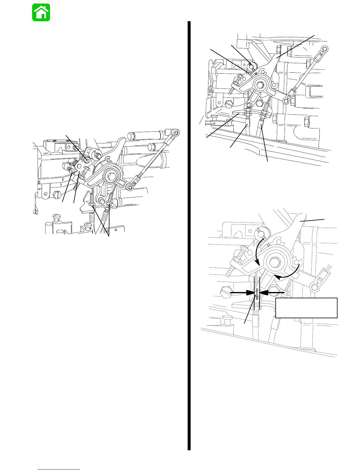
a - Idle Speed Screw
b - Cam Follower Screw
c - Throttle Shutter Positioner
d - Jam Nuts
4. With throttle at idle position, place cam follower
roller against throttle cam. Center the roller with
raisedmarkonthrottlecambyadjustingtheposi-
tion of throttle cable sleeves in the mounting
bracket on tiller handle models or throttle linkrod
on remote control models.
NOTE: When positioning throttlecables, a minimum
of 1/16 in. (1.59 mm) to a maximum of 1/8 in. (3.18
mm)slackmust beallowed to preventthrottlecables
from binding. (Rock throttle cam side to side and
measure the amount of throttle cam travel at link rod
ball.
5. Tighten throttle cable jam nuts.
55762
a
b
c
d
e
d
a - Cam Follower Screw
b - Cam Follower Roller
c - Throttle Cam
d - Throttle Cable Sleeve
e - Mounting Bracket
55762
Cable Slack
Min. 1/16 in. (1.59 mm)
Max. 1/8 in. (3.18 mm)
a
b
a - Link Rod Ball
b - Throttle Cam
6. With cam follower resting on throttle cam, tighten the
cam follower screw.

 Loading...