90-826148R2 MARCH 1997 ELECTRICAL - 2D-23
Route TAN lead on starboard side of engine to engi-
ne/remote control harness. Connect as shown.
IMPORTANT: Tape back and isolate any unused
wiring harness leads.
28086
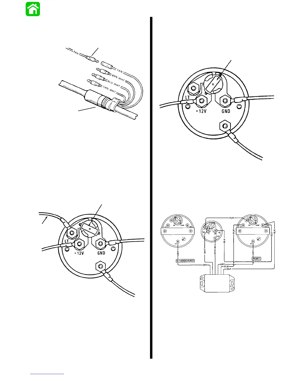
a
b
a - Lead from Temperature Sender
b - Engine/Remote Control Harness
Engine Synchronizer Wiring Diagram
LIGHT BULB POSITION A
Use this position when using a separate light switch
for instrument lighting.
Position Light Bulb to the
Unswitched Position
+ 12 Volt
Light Switch
Wire
SEND
51105
LIGHT BULB POSITION B
Usethispositionwheninstrumentlightingiswireddi-
rectlytotheignitionkeyswitch.(Instrumentlightsare
on when ignition key switch is turned on.)
SEND
Position Light Bulb to the
Switched Position
51106
Synchronizer wiring can beaccomplished twodiffer-
ent ways as an option to the user.
Wiring Diagram -- Gauge needle to point toward
slow running engine
52566
Tachometer
Starboard Engine
Synchronizer
Gauge
Tachometer
Port Engine
Synchronizer
Box

 Loading...