90-826148R2 MARCH 19972D-22 - ELECTRICAL
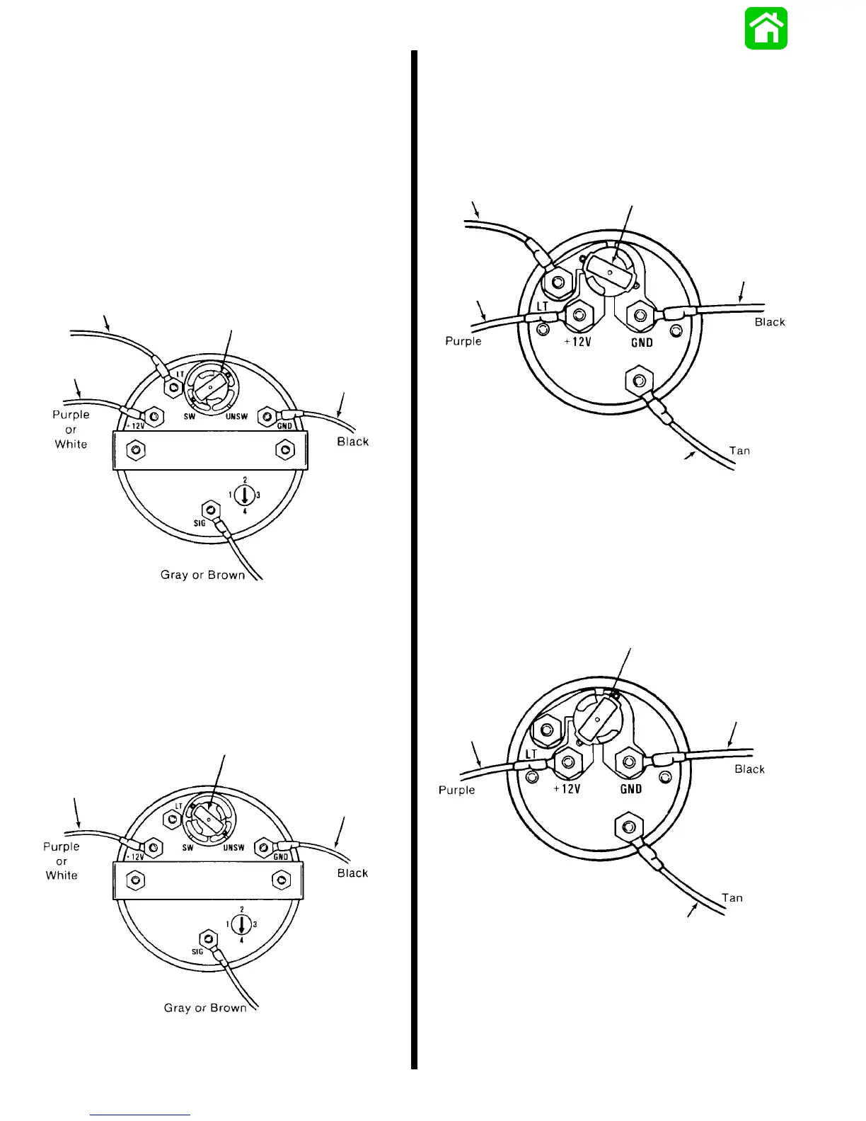
QSI Gauge Wiring Diagrams
Tachometer Wiring Diagram
Tachometer dial on back side of case must be set to
position number 4.
WIRING DIAGRAM A
Use this wiring diagram when using a separate light
switch for instrument lighting.
+12 Volt
Light Switch
Wire
Position Light Bulb to the
Switched Position
Connect to
Negative (--)
Ground
Connect to
+ 12 Volt
51106
WIRING DIAGRAM B
Use this wiring diagram when instrument lighting is
wired directly to the ignition key switch. (Instrument
lights are on when ignition key switch is turned on.)
51106
Position Light Bulb to the
Unswitched Position
Connect to
+ 12 Volt
Ground
Connect to
Negative (--)
Water Temperature Gauge
WIRING DIAGRAM A
Use this wiring diagram when using a separate light
switch for instrument lighting.
+12 Volt
Light Switch
Wire
Position Light Bulb to the
Switched Position
Connect to
Negative (--)
Ground
Connect to Tan Lead Located
at the Tachometer Receptacle on
Commander Side Mount Remote
Control or Tan Lead Coming From
Accessory Ignition/Choke Assembly
Connect to
+ 12 Volt
SEND
WIRING DIAGRAM B
Use this wiring diagram when instrument lighting is
wired directly to the ignition key switch. (Instrument
lights are on when ignition key is turned on.)
51105
Position Light Bulb to the
Unswitched Position
Connect to
Negative (--)
Ground
Connect to Tan Lead Located
at the Tachometer Receptacle on
Commander Side Mount Remote
Control or Tan Lead Coming From
Accessory Ignition/Choke Assembly
Connect to
+ 12 Volt
SEND

 Loading...