2B-10 - ELECTRICAL 90-826148R2 MARCH 1997
Starting System
Starter Motor Amperes Draw
Starter Motor Part
No.
No Load
Amp. Draw
Normal
Amp. Draw
50-822462 20 Amps 95 Amps
Starter Motor Teeth 10
Starting System Components
The starting system consists of the following compo-
nents.
1. Battery
2. Starter Solenoid
3. Neutral Start Switch
4. Starter Motor
5. Ignition Switch
Description
The function of the starting system is to crank the en-
gine. The battery supplies electrical energy to crank
the starter motor. When the ignition switch is turned
to “START” position, the starter solenoid is activated
and completes the starting circuit between the bat-
tery and starter.
The neutral start switch opens the start circuit when
the shift control lever is not in neutral. This prevents
accidental starting when engine is in gear.
CAUTION
The starter motor may be damaged if operated
continuously. DO NOT operate continuously for
more than 30 seconds. Allow a 2 minute cooling
period between starting attempts
.
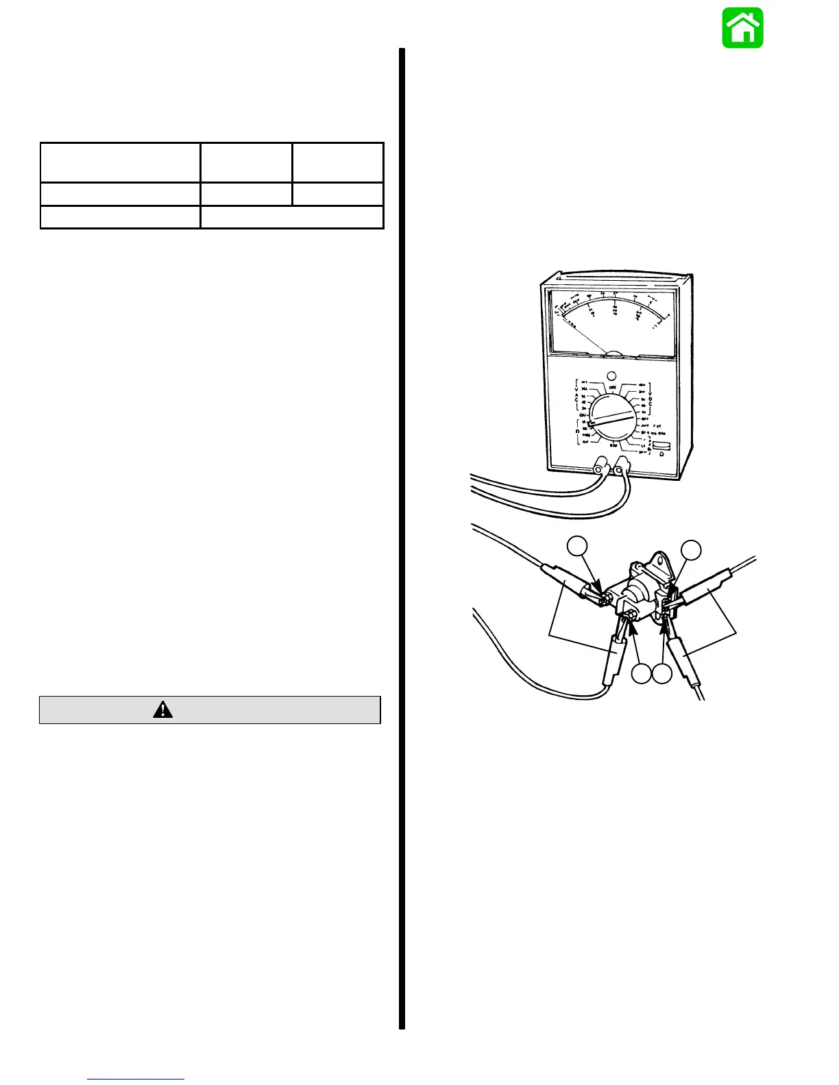
STARTER SOLENOID TEST
Test starter solenoid as follows:
1. Disconnect all leads from solenoid terminals.
2. Use an ohmmeter, set to (R x 1 scale) and con-
nect between solenoid terminals 3 and 4.
3. Connect a 12-volt supply between solenoid ter-
minals 1 and 2. Solenoid should click and meter
should read zero ohms.
4. If meter does not read zero ohms (full continuity),
replace solenoid.
14354
1
2
3
4
a
b
a - Ohmmeter Leads
b - 12-Volt Supply
Troubleshooting the Starting Circuit
Before beginning the starting circuit troubleshooting
flow chart, following, check first for the following con-
ditions:
1. Make sure that battery is fully charged.
2. Check that control lever is in “NEUTRAL” posi-
tion.
3. Check terminals for corrosion and loose connec-
tions.
4. Check cables and wiring for frayed and worn in-
sulation.
5. Check in-line fuse in RED wire; see diagram.

 Loading...