4-12 - POWERHEAD 90-826148R2 MARCH 1997
NOTE: Refer to appropriate sections in service
manual for removal of individual fuel and electrical
sub-assemblies from powerhead.
Component/Assembly Section
Starter Motor 2B
Ignition Switch Box 2A*
Ignition Coil 2A*
Starter Solenoid 2B*
Voltage Regulator/Rectifier 2B*
Flywheel 2A
Stator Assembly 2A*
Trigger Assembly 2A*
Air Silencer 3B
Carburetor and Linkage 3B
Fuel Pump 3A
Fuel Enrichment Valve 3B
Shift Cable Latch Assembly 7A
Control Cable Anchor Bracket 7A
Warning Module 3C*
Oil Pump 3C
*NOTE:Allignitionandelectricalcomponentscanbe
removed and installed as an assembly.
Crankshaft Disassembly
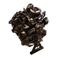
1. Remove center main bearing.
52906
2. Removerodcapboltsandkeepcomponentswith
respective connecting rod. Reattach caps to re-
spective rod as each piston/rod assembly is re-
moved. CAPS MUST BE INSTALLED IN SAME
DIRECTION ON SAME ROD or BEARING
FAILURE WILL RESULT.
52907
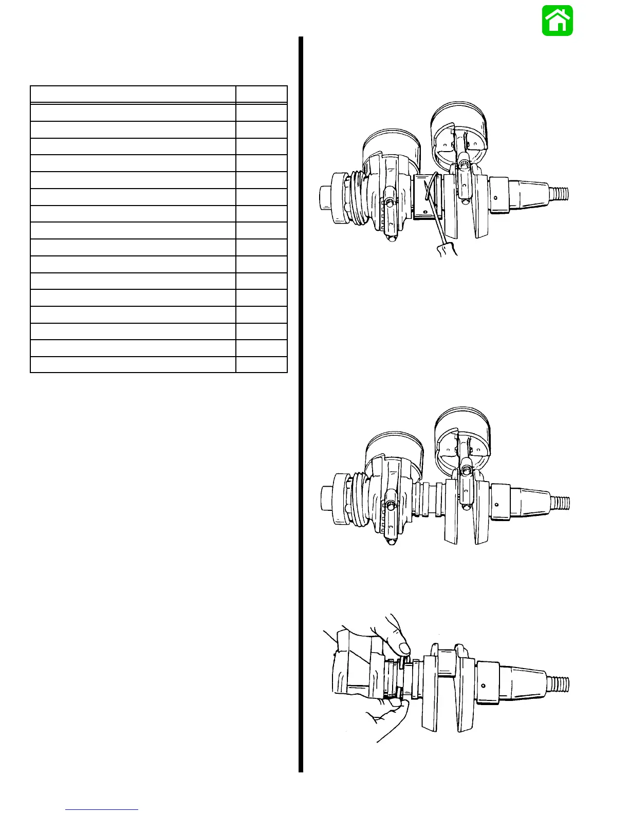
3. Remove main bearing sealing ring.
52908

 Loading...