2B-6 - ELECTRICAL 90-826148R2 MARCH 1997
Alternator System Test
9 AMPERE STATOR
IMPORTANT: Rectifier (optional accessory) must
be functioning properly for accurate test results
to be obtained.
1. Remove RED lead from (+) terminal of rectifier.
2. Connect RED (+) ammeter lead to rectifier (+) ter-
minal and BLACK (–) ammeter lead to RED recti-
fier lead.
3. With engine running at the indicated RPM, the
ammeter should indicate the following approxi-
mate amperes:
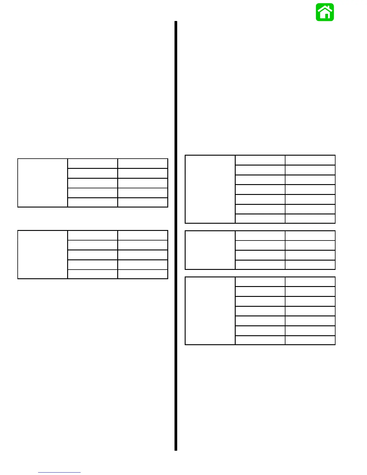
9 AMPERE STATOR (S/N-0G589999 & BELOW)
RPM AMPERES
9 Am
ere
Idle 0
Stator
1000 0.2
2000 6.5
3000 9.0
9 AMPERE STATOR (S/N-0G590000 & ABOVE)
RPM AMPERES
Am
ere
Idle 0
Stator
1000 0.6
2000 8.0
3000 9.0
4. If proper ampere readings are not obtained, re-
place stator.
14/16/18 AMPERE STATOR
1. Check battery voltage at battery with engine run-
ning.
2. If battery voltage is above 14.5 volts, replace volt-
age regulator/rectifier. Check condition of battery
as overcharging may have damaged battery.
3. If battery voltage is below 14.5 volts, charge bat-
tery; refer to “CHARGING A DISCHARGED BAT-
TERY”. If battery can NOT be satisfactorily
charged, replace battery.
4. If battery accepts a satisfactory charge, check
battery voltage while cranking engine; refer to
“CHARGING A DISCHARGED BATTERY”. If
cranking voltage is not acceptable, replace bat-
tery.
5. If cranking voltage is acceptable, disconnect
larger diameter RED harness wire from starter
solenoid terminal.
6. Remove smaller diameter RED wire (sense lead)
from starter solenoid terminal and connect to the
positive (+) terminal of a 9 volt transistor battery.
Ground the negative (–) terminal of the 9 volt bat-
tery to the engine.
7. Connect RED (+) ammeter lead to larger diame-
ter RED harness wire, and BLACK (–) ammeter
lead to POSITIVE terminal on starter solenoid.
8. Secure starter wires away from flywheel.
9. With engine running at the indicated RPM’s, the
ammeter should indicate the following appropri-
ate amperes:
RPM AMPERES
Idle 2
1000 7
mpere
2000 12
3000 13
4000 13.5
5000 14
RPM AMPERES
16 Am
ere
Idle 2.8
Stator
1000 9.3
2000 16
RPM AMPERES
Idle 3
1000 9.5
mpere
2000 17
3000 18
4000 18
5000 18
 Loading...