Rectifier Test (continued)
Connect red meter lead to ground, black lead alternately
to terminals “a” and “c”.
Connect black meter lead to ground, red lead
alternately to terminals “a” and “c”.
Connect black meter lead to ground, red lead
alternately to terminals “a” and “c”.
Continuity Indicated No Continuity Indicated
Continuity Indicated.
Replace Rectifier.
Continuity Indicated.
Replace Rectifier.
Continuity Indicated.
Rectifier Tests O.K.
Continuity Indicated.
Replace Rectifier.
No Continuity Indicated.
Replace Rectifier.
No Continuity Indicated.
Replace Rectifier.
No Continuity Indicated.
Replace Rectifier.
No Continuity Indicated.
Rectifier tests O.K.
Continuity Indicated
Continuity Indicated
No Continuity Indicated
No Continuity Indicated
Connect red meter lead to terminal “b”,
black lead alternately to terminals “a”
and “c”.
Connect red meter lead to terminal “b”,
black lead alternately to terminals “a”
and “c”.
Connect black meter lead to terminal “b”, red
lead alternately to terminals “a” and “c”.
Connect black meter lead to terminal “b”, red
lead alternately to terminals “a” and “c”.
2B-8 - ELECTRICAL 90-826148R2 MARCH 1997
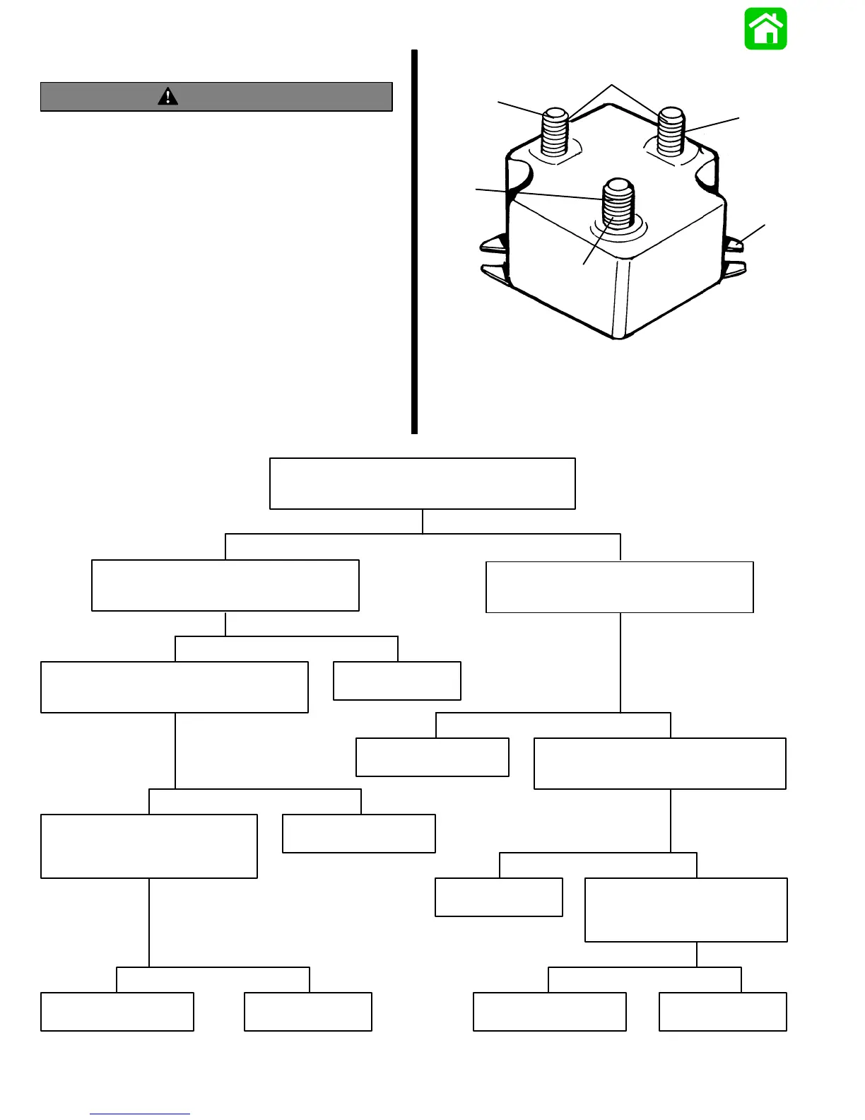
Rectifier Test
WARNING
Disconnect battery leads from battery before
testing rectifier.
NOTE: Rectifier can be tested without removing from
engine.
1. Disconnect all wires from terminals on rectifier.
2. Use an ohmmeter (R x 1000 scale) and perform
the following test. Refer to drawing for rectifier
terminal identification.
07300
a
b
c
d
e
f
a - Terminal
b - Terminal
c - Terminal
d - Stator Terminals
e - Positive Terminal
f - Ground

 Loading...