10 Buffer Memory
10.4 I/O signals to PLC
101
FX3U-16CCL-M User's Manual
1
Introduction
2
Specification
3
System
Configuration
4
Installation
5
Wiring
6
Introduction of
Functions
7
Data Link
Processing
Time
8
Parameter
Setting
9
Data Link
Procedure
10
Buffer Memory
10.4 I/O signals to PLC
This section describes I/O signals used to control the master block.
The signals used to control the master block are assigned to the buffer memory (BFM#10 and BFM#11) built
in the FX3U-16CCL-M. The buffer memory of the same number works differently between the time of read
(when the FROM instruction is used) and the time of write (when the TO instruction is used) as shown in the
table below.
The system automatically changes over these functions in accordance with the instruction (FROM or TO).
Caution
The output signals prohibited in the table below are used by the system, thus cannot be accessed by the
user.
If used, normal operations cannot be guaranteed.
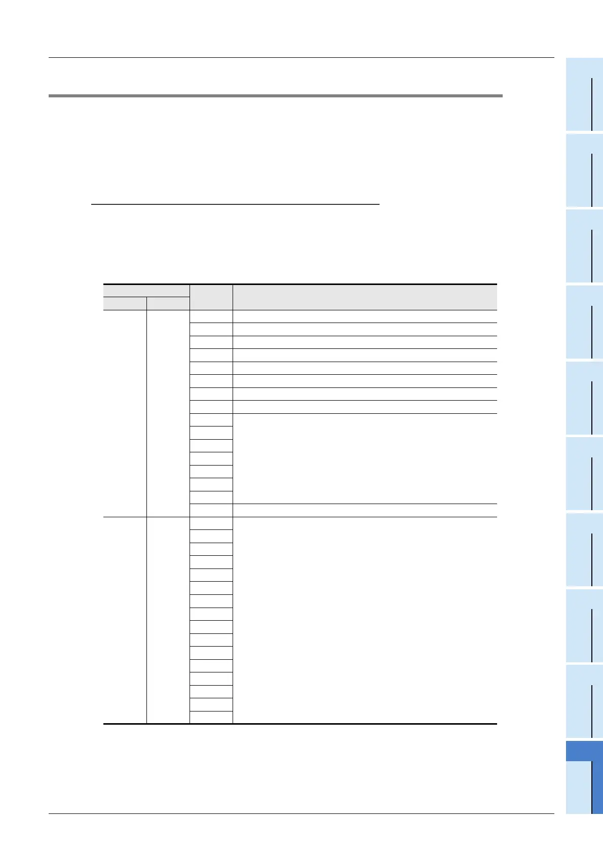
I/O signals list
•PLC
← Master block : Read (when FROM instruction is used)
BFM No.
Bit Input signal name
Hex. Dec.
#AH #10
b0 Unit error
b1 Data link status in master station
b2 Parameter setting status
b3 Data link status in other stations
b4 Use prohibited
b5 Use prohibited
b6 Normal completion of data link startup by buffer memory parameters
b7 Abnormal completion of data link startup by buffer memory parameters
b8
Use prohibited
b9
b10
b11
b12
b13
b14
b15 Unit ready
#BH #11
b0
Use prohibited
b1
b2
b3
b4
b5
b6
b7
b8
b9
b10
b11
b12
b13
b14
b15

 Loading...


