15 Example of Communication in Compound System
15.3 When Remote Net Additional Mode is Used
233
FX3U-16CCL-M User's Manual
11
Programming
12
Remote I/O
Communication
Example
13
Remote Device
Communication
Example
14
Int. Device
Communication
Example
15
Compound Sys.
Communication
Example
16
Troubleshooting
A
Version
Information
B
Setting Sheet
C
Differences with
FX
2N
-16CCL-M
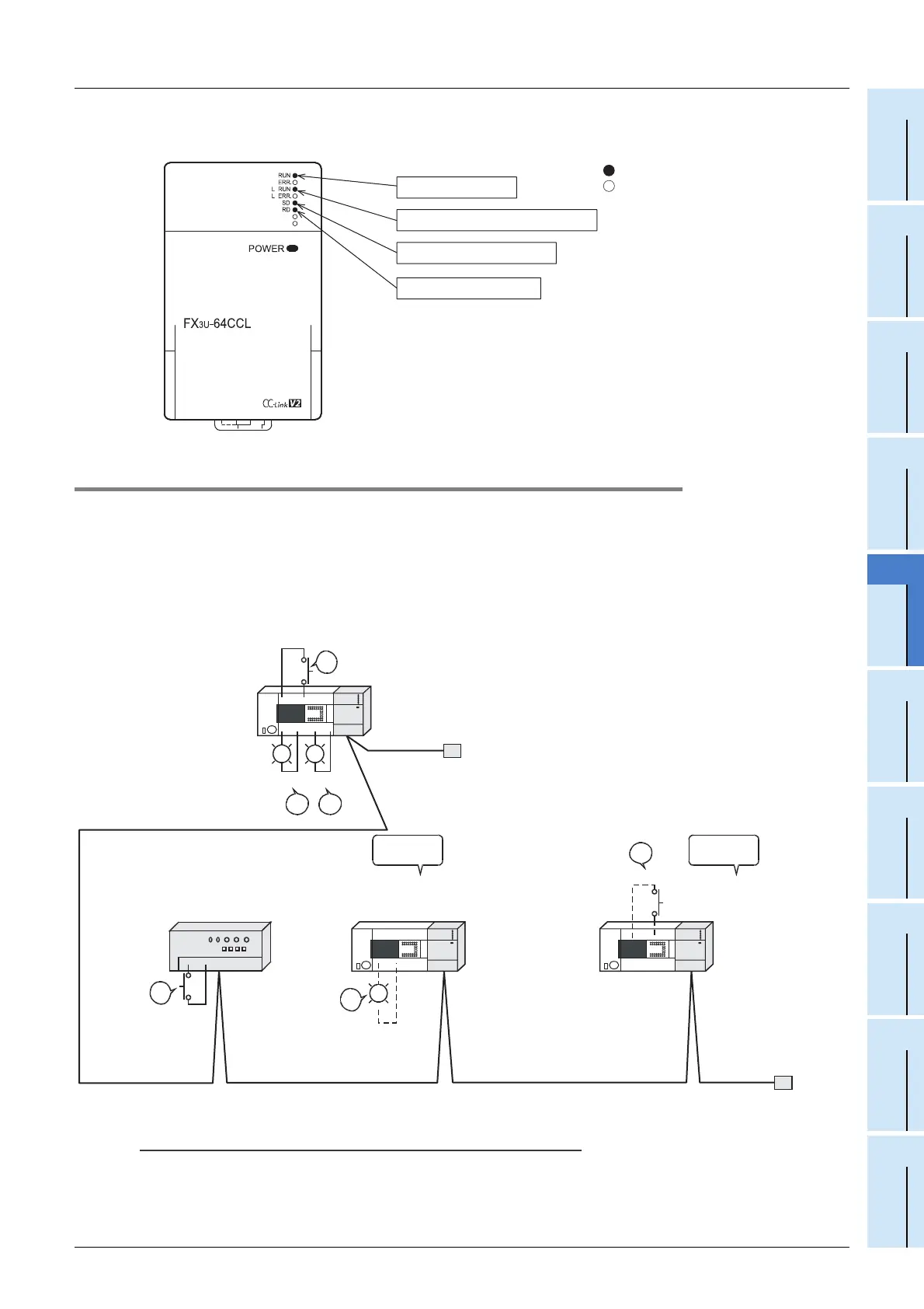
• LED indication in the intelligent device station (FX3U-64CCL)
Make sure that the LED indication status is as shown below.
15.3.10 Confirmation of operation by program
Using a sequence program, make sure that data link is normally proceeding.
1) When the input X00 in the AJ65BTB1-16D (station No. 1) is set to ON, the output Y000 in the master
station PLC turns ON.
2) When X000 in the master station PLC turns ON, RY00 in the FX
2N-32CCL (station No. 2) turns ON.
3) When RX40 in the FX
3U-64CCL (station No. 3) turns ON, Y060 (M164) in the master station PLC turns
ON.
Caution
A program for communication is required also in the FX
3U Series main unit connected to the FX2N-32CCL
and FX
3U-64CCL.
The unit is normal.
Data link is normally proceeding.
Data is being transmitted.
Data is being received.
: On
: Off
X00
ON
1)
RX40
3)
ON
1)
Y000
3)
Y060
ON ON
X000
ON
2)
RY20
ON
2)
FX3U Series
Main unit
Master station
FX
3U-16CCL-M
Terminal
resistor
AJ65BTB1-16D
Input unit
Ver. 1 compatible
Remote I/O station
(station No. 1)
Ver. 1 compatible
Remote device station
(station No. 2)
FX
3U Series
Main unit
Ver. 2 compatible
Intelligent device station
(station No. 3)
FX
2N-32CCL
CC-Link interface block
FX
3U-64CCL
CC-Link interface block
FX
3U Series
Main unit
Terminal
resistor
Occupies
2 stations.
Occupies
1 station.

 Loading...


