4 Installation
4.2 Direct Mounting
34
FX3U-16CCL-M User's Manual
4.2 Direct Mounting
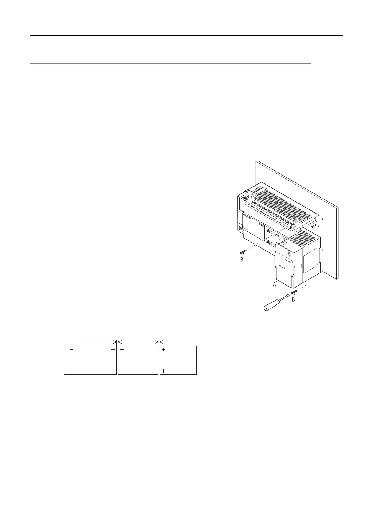
The product can be installed directly with screws.
An interval space of 1 to 2 mm (0.04" to 0.08") between each unit is necessary.
For installation details, refer to the following respective PLC manual.
→ For mounting hole pitches, refer to Section 1.2.
→ Refer to the FX
3G Hardware Edition.
→ Refer to the FX
3U Hardware Edition.
→ Refer to the FX
3UC Hardware Edition.
1 Create mounting holes in the mounting
surface according to the external dimensions
diagram.
2 Fit the FX
3U
-16CCL-M (A in the figure to the
right) to the mounting holes and tighten with
M4 screws (B in the figure to the right).
For the screw position and quantity, refer to the
dimensioned drawing specified below.
→ For dimensions, refer to Section 1.2.
3 Connect the extension cable.
Connect the extension cable to the main unit, I/O
extension unit/block or special function unit/block on the left
side of the product.
(Refer to Step 3 in Section 4.1.)
For information on the extension cable connection
procedure, refer to the respective PLC manual.
→ Refer to the FX3G Hardware Edition.
→ Refer to the FX
3U Hardware Edition.
→ Refer to the FX
3UC Hardware Edition.
• Example of direct installation
FX3G/FX3U Series
main unit
1 to 2mm
(0.04" to 0.08")
1 to 2mm
(0.04" to 0.08")
(+ shows the M4 screw)
other
extension
equipment
FX3U-16CCL-M

 Loading...


