1 Introduction
1.3 Terminal Layout
19
FX3U-16CCL-M User's Manual
1
Introduction
2
Specification
3
System
Configuration
4
Installation
5
Wiring
6
Introduction of
Functions
7
Data Link
Processing
Time
8
Parameter
Setting
9
Data Link
Procedure
10
Buffer Memory
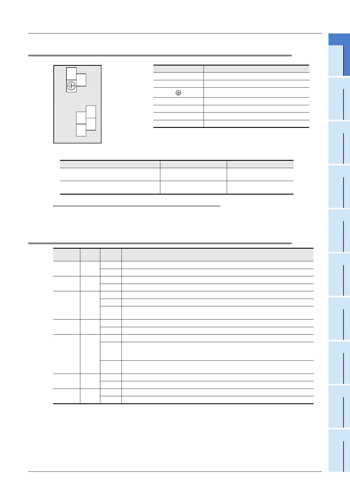
1.3 Terminal Layout
• Terminal screw and terminal block mounting screw size, and tightening torque
Caution
CC-Link connection terminal block can be detached or attached. Make sure to cut off all phases of the power
supply externally.
1.4 Power and Status LEDs
Terminal name Description
24+ 24 V DC power supply, + side
24- 24 V DC power supply, - side
Ground terminal (Functional ground)
DA Send/receive data
DB Send/receive data
DG Data ground
SLD Shield
Terminal name Terminal screw size Tightening torque
Power supply terminal block, CC-Link connection
terminal block
M3 screw 0.42 to 0.58 N
•
m
CC-Link connection terminal block mounting
screw (black)
M3.5 screw 0.66 to 0.91 N
•
m
LED
display
LED
Color
Status Description
POWER Green
OFF Power is not being supplied from the external power supply (24 V DC).
ON Power is being supplied from the external power supply (24 V DC).
RUN Green
OFF FX3U-16CCL-M has failed.
ON Under FX3U-16CCL-M normal operation.
ERR. Red
OFF No errors.
Flicker Communication error has occurred in some stations.
ON
Communication error has occurred in all stations, error in the settings, error in the parameter
details, error with the communication, error with the H/W.
L RUN Green
OFF Offline.
ON Data link is being executed (host station).
L ERR. Red
OFF No communication error.
Flicker
The switch setting was changed after start.
There is no terminating resistor.
Influence from noise.
ON
There is a data linking error (host station).
There is a setting error.
SD Green
OFF Data is not being sent.
ON Data is being sent.
RD Green
OFF Data is not being received.
ON Data is being received.
CC-Link connection
terminal block
Power supply
terminal block
24+
24-
DA DB
SLDDG

 Loading...


