3 System Configuration
29
FX3U-16CCL-M User's Manual
1
Introduction
2
Specification
3
System
Configuration
4
Installation
5
Wiring
6
Introduction of
Functions
7
Data Link
Processing
Time
8
Parameter
Setting
9
Data Link
Procedure
10
Buffer Memory
3.4 Number of Occupied Stations and Station numbers as well as Number of Units and Number of Stations
3.4 Number of Occupied Stations and Station numbers as well as Number
of Units and Number of Stations
This section describes the relationship between the number of occupied stations and the station number as
well as between the number of units and the number of stations.
1. Number of occupied stations
It is the number of stations on the network which a single remote device station or intelligent device station
use. According to the number of data, 1 to 4 stations can be set.
However, a remote I/O station can only occupy 1 station.
2. Station Number
The station number of the master station is 0.
The station number of the remote stations and intelligent device station are assigned between 1 to 16. If there
is a station unit occupying 2 or more stations, the number of occupied stations should be taken into account
when the station numbers are assigned.
3. Number of units and number of stations
The number of units indicates the number of physical modules.
The number of stations indicates the number of stations occupied by remote stations and intelligent device
stations.
3.5 Precautions When Configuring the System
Design the system with the following considerations to prevent erroneous inputs from remote I/O units.
1. Timing of power ON and power OFF
Turn on the power of remote I/O units first, then start the data link.
Stop the data link first, then turn off the power of remote I/O units.
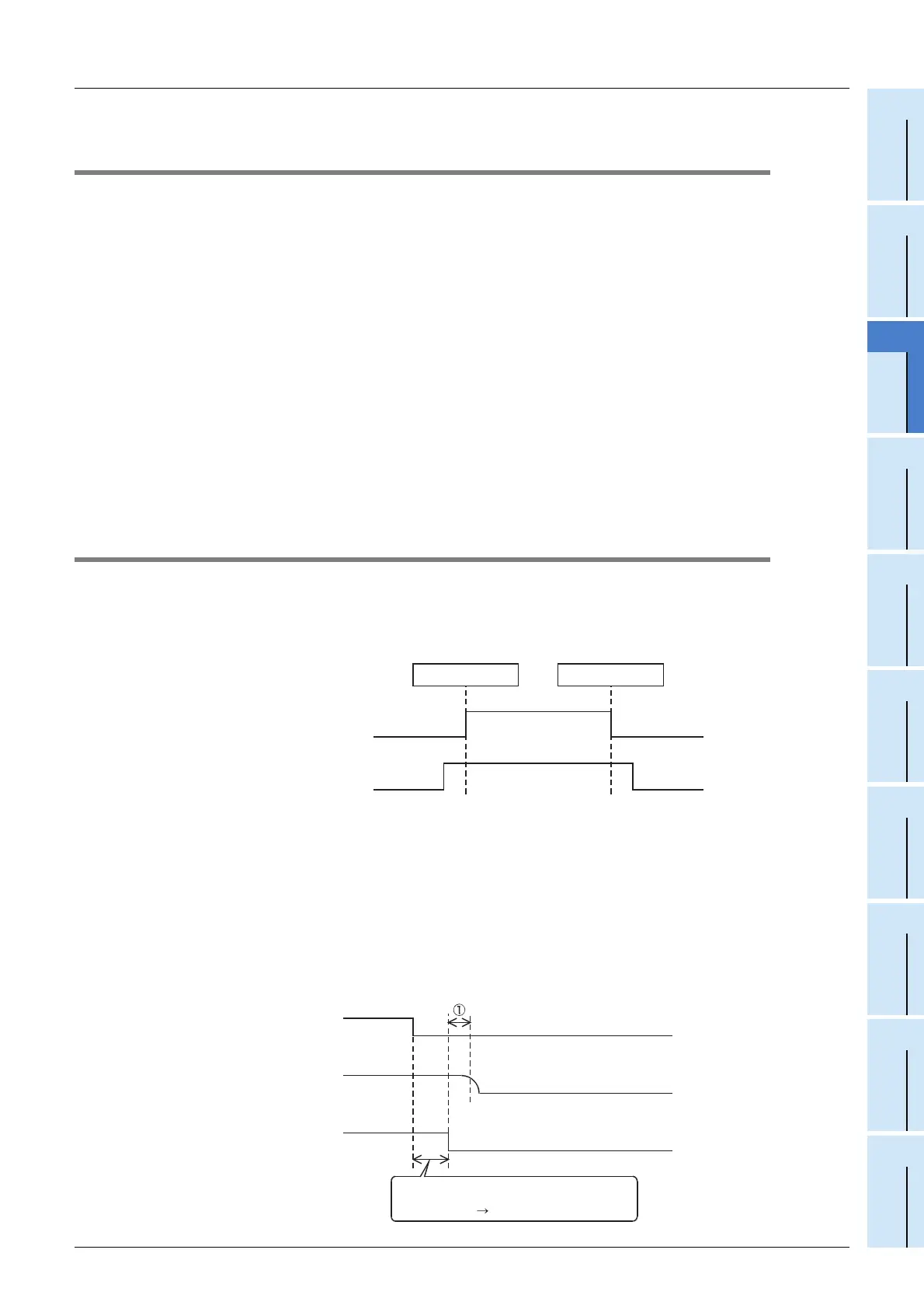
2. Momentary power failure in remote I/O units
When momentary power failure occurs in the power (24 V DC) supplied to remote I/O units, erroneous input
may occur.
1) Cause for erroneous input due to momentary power failure
The remote I/O unit hardware converts the module power (24 V DC) into 5 V DC inside the module, then
uses the 5 V DC.
When momentary power failure occurs in a remote I/O unit, the following condition occurs:
(Time until 5 V DC inside remote I/O unit turns off) > (Input unit ON → OFF response time)
Therefore, erroneous input is caused when refresh is executed within the period of time indicated by ➀ in
the diagram below.
Remote I/O unit
(power supply status)
During operation
During stop
Master block
(data link status)
ON
OFF
Data link start Data link stop
Remote I/O unit
(internal 5 V DC)
Remote I/O unit
(unit power supply and input
external power supply)
Because the input external power supply is
turned off, the input (X) turns off after the
"input unit ON
OFF response time".
Input (X)

 Loading...


