14 Example of Communication between Master Station
14.2 When Remote Net Ver. 2 Mode is Used
193
FX3U-16CCL-M User's Manual
11
Programming
12
Remote I/O
Communication
Example
13
Remote Device
Communication
Example
14
Int. Device
Communication
Example
15
Compound Sys.
Communication
Example
16
Troubleshooting
A
Version
Information
B
Setting Sheet
C
Differences with
FX
2N
-16CCL-M
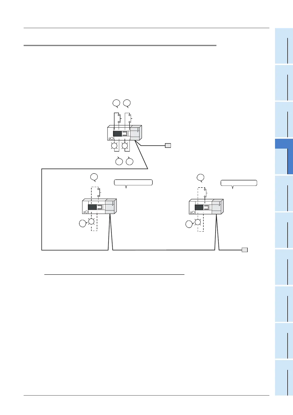
14.2.8 Confirmation of operation by program
Using a sequence program, make sure that data link is normally proceeding.
1) When X000 in the master station PLC turns ON, RY00 in the FX
3U-64CCL (station No. 1) turns ON.
2) When RX00 in the FX
3U-64CCL (station No. 1) turns ON, Y000 (M100) in the master station PLC turns
ON.
3) When X001 in the master station PLC turns ON, RY40 in the FX
3U-64CCL (station No. 4) turns ON.
4) When RX60 in the FX
3U-64CCL (station No. 3) turns ON, Y001 (M196) in the master station PLC turns
ON.
Caution
A program for communication is required also in the FX
3U Series main unit connected to the FX3U-64CCL.
Occupies 1 station.
Occupies 3 stations.
X000
1)
X001
3)
ON
ON
2)
Y000
4)
Y001
ON
ON
RX00
2)
ON
RX60
4)
ON
RY00
ON
1)
RY60
ON
3)
Terminal
resistor
Ver. 2 compatible Intelligent
device station (station No. 4)
Ver. 1 compatible Intelligent device station
(station No. 1)
Terminal
resistor
FX3U Series
Main unit
Master station
FX
3U-16CCL-M
FX
3U Series
Main unit
FX3U-64CCL
CC-Link interface block
FX3U Series
Main unit
FX3U-64CCL
CC-Link interface block

 Loading...


