15 Example of Communication in Compound System
15.3 When Remote Net Additional Mode is Used
232
FX3U-16CCL-M User's Manual
15.3.8 Execution of data link
Turn on the power of the units in the order "remote I/O station, remote device station, intelligent device station
→ master station", then start the data link.
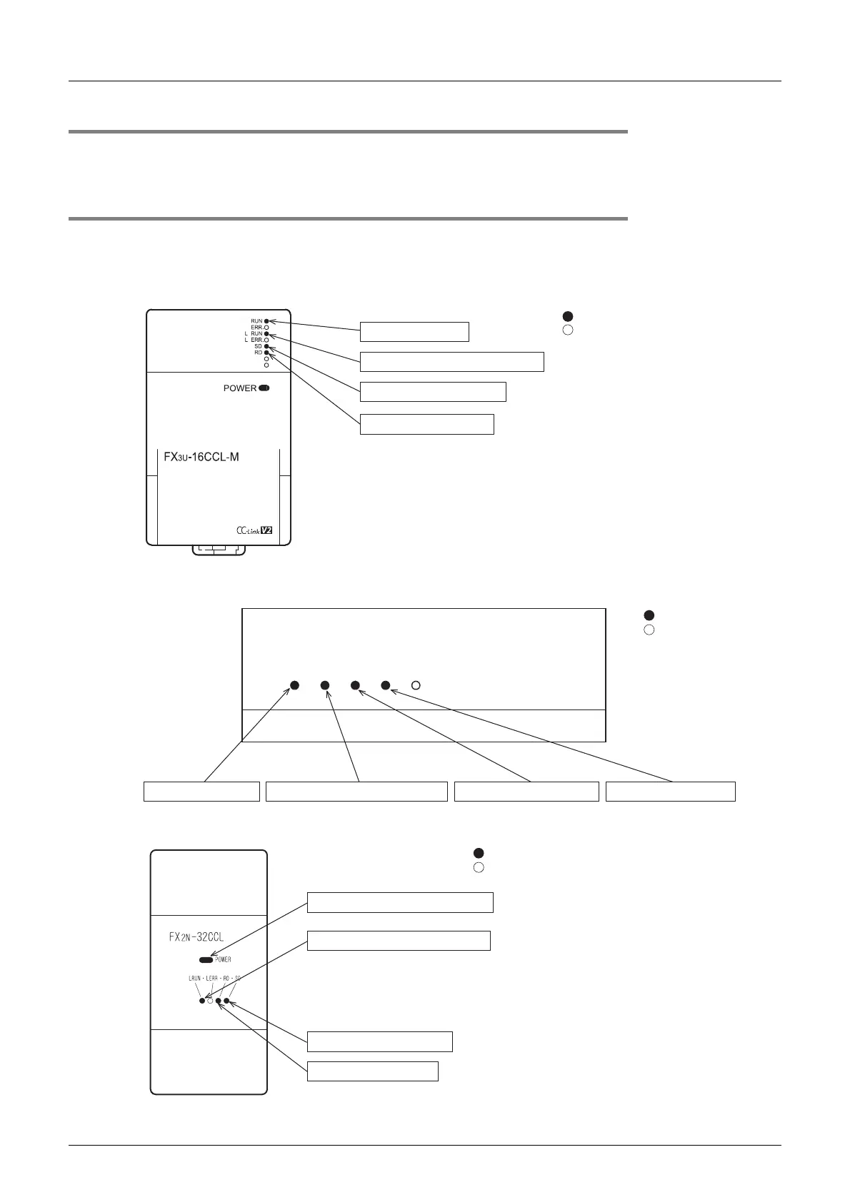
15.3.9 Confirmation of operation by LED indication
The figures below show the LED indication status in the master station, the remote I/O station, the remote
device station and intelligent device station while the data link is normally proceeding.
• LED indication in the master station
Make sure that the LED indication status is as shown below.
• LED indication in the remote I/O station
Make sure that the LED indication status is as shown below.
• LED indication in the remote device station
Make sure that the LED indication status is as shown below.
The unit is normal.
Data link is normally proceeding.
Data is being transmitted.
Data is being received.
: On
: Of
A
J65BTB1-16D
PW L RUN SD RD L ERR.
: On
: Off
24 V DC is supplied.
Data link is normally proceeding.
Data is being transmitted. Data is being received.
5 V DC is supplied from the PLC.
: On
: Off
Data link is normally proceeding.
Data is being transmitted.
Data is being received.

 Loading...


