9 Data Link Procedure
9.1 Data Link Procedure
87
FX3U-16CCL-M User's Manual
1
Introduction
2
Specification
3
System
Configuration
4
Installation
5
Wiring
6
Introduction of
Functions
7
Data Link
Processing
Time
8
Parameter
Setting
9
Data Link
Procedure
10
Buffer Memory
9.1 Data Link Procedure
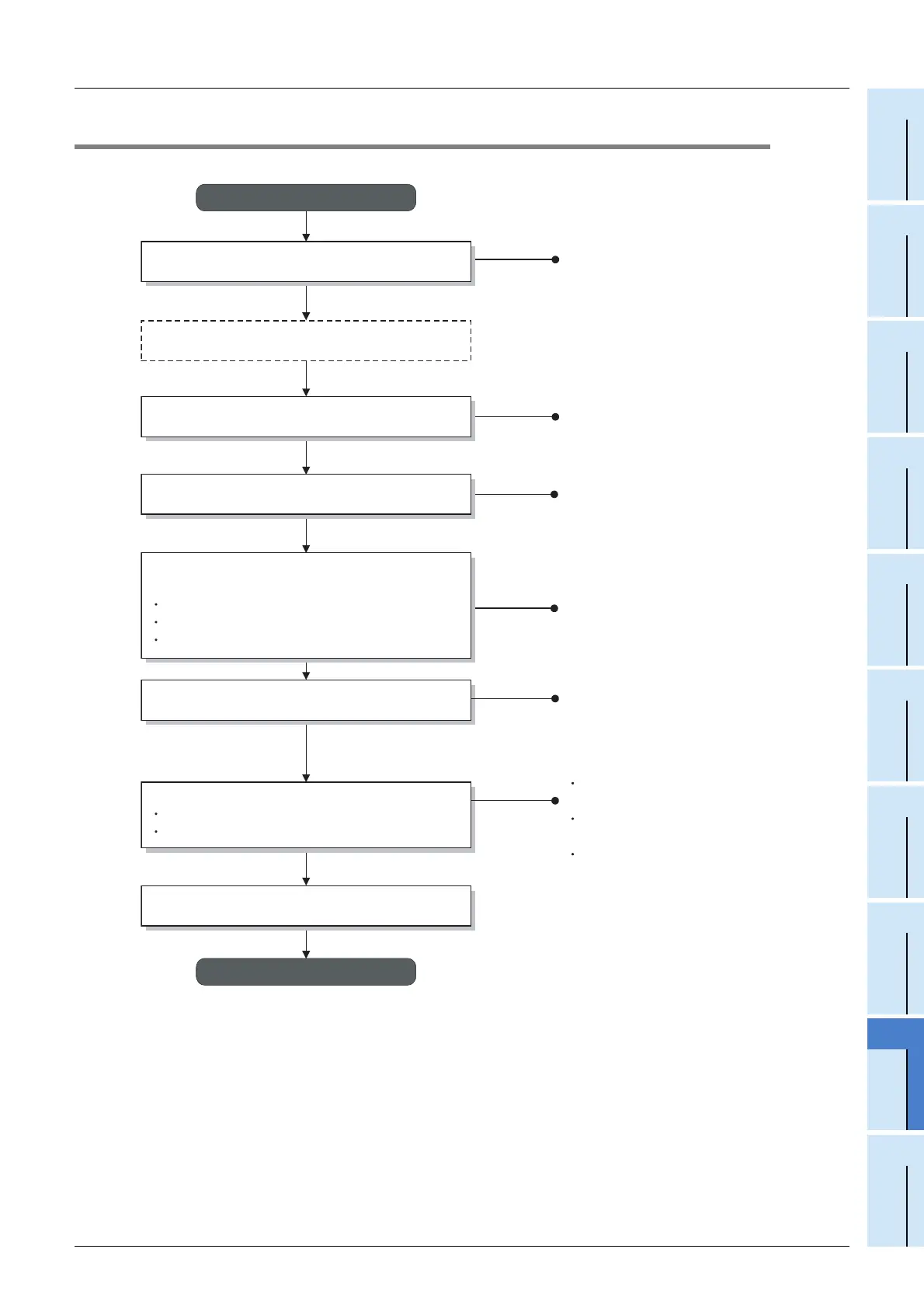
The flowchart below shows the procedure for data link in the CC-Link system.
Attach remote stations and intelligent device
stations to the control panel and the machine.
Connect each unit with CC-Link cables.
Start
For the connect with CC-Link cables,
refer to Section 5.2.
For the installation procedure,
refer to Chapter 4.
Connect the PLC and the master block.
For the hardware test, refer to Section 9.2.
Start data link.
Check the connection status of each unit
(line test).
For the line test, refer to Subsection 9.4.
Set switches in the FX
3U
-16CCL-M and remote
units.
Station No. setting switch
Mode setting switch
Transmission rate setting switch
For switch setting, refer to Section 9.4.
Programming
Program for parameter setting
Program for communication
For the program for parameter setting,
refer to Chapter 8.
For the program for communication,
refer to Chapter 12 to 15.
For the precautions in programming,
refer to Chapter 11.
End
Check if the FX
3U
-16CCL-M operates normally
(hardware test).

 Loading...


