17.
17 - 8
BASE UNIT AND EXTENSION CABLE
17.5 Part Names
Part names of the base unit are shown here.
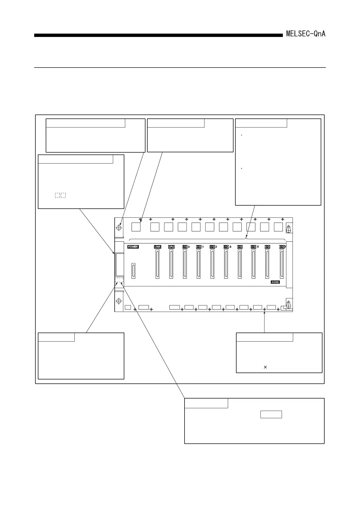
(1) Main base units (A32B, A35B, A38B, A38HB, A38HBEU)
Extension cable connector
POINT
In the case of the A38HB, A38HB is printed
beneath the base cover. The A38B has no print
here. Use this as a means of distinguishing
between base units when mounting modules.
Connector for sending and
receiving signals to and from
the extension base unit.
Connect the extension cable
(AC B). (The A32B is not
provided with a connector.)
Guide hole for base installation
A bell-shaped hole used to install
the base unit to a control panel.
(For M5 screw)
Module fixing cutout
The projection and hook on
rear of a module are inserted
for fixing the module.
Module fixing screwBase cover
A protective cover for the
connector for the extension
cable. To connect an extension,
the top of the connector has to
be removed with a tool such as
nippers.
Module connector
Connectors where the
power supply module,
CPU module, I/O modules,
and special function
modules are loaded.
To prevent dust from entering
the connector with no module
installed, attach the supplied
blind cap, blank cover (AG60),
or dummy module (AG62).
Modules can be fixed with a
screw in addition to the
module fixing hook. Screw
size: M4 0.7 screw
 Loading...

