22 - 22
22. TROUBLE SHOOTING
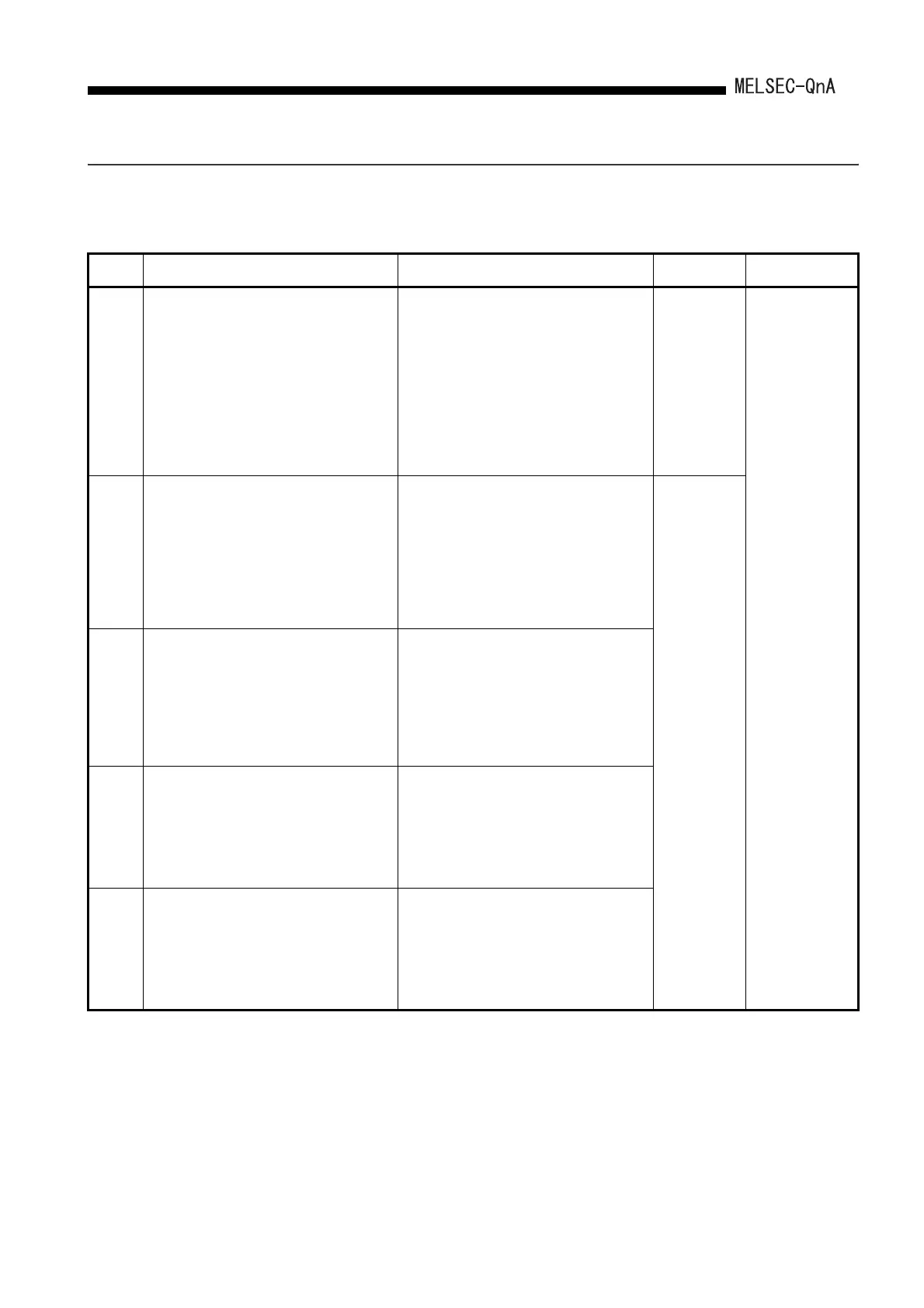
22.3.4 Error code list (2000 to 2999)
The following shows the error messages from the error code 2000 to 2999, the contents
and causes of the errors, and the corrective actions for the errors.
Error
Code
Error Contents and Cause Corrective Action
LED Status
CPU Status
Corresponding
CPU
2000
[UNIT VERIFY ERR.]
I/O module information power ON is changed.
• I/O module (or special function module) not
installed properly or installed on the base unit.
■Collateral informationmmon
• Common Information:Module No.(Slot No.)
[For Remote I/O network]
Network No./Station No.
• Individual Information:–
■Diagnostic Timing
• When an END instruction executed
• Read the common information of the error using
the peripheral device, and check and/or change
the module that corresponds to the numerical
value (module number) there.
• Alternatively, monitor the special registers
SD1400 to SD1431 at a peripheral device, and
change the fuse at the output module whose bit
has a value of "1".
• When a GOT is bus-connected to the main base
unit or extension base unit, check the connection
status of the extension cable and the grounding
status of the GOT.
RUN:
Off/On
ERR.:
Flicker/On
CPU Status:
Stop/
Continue
*1
QnA
2100
[SP. UNIT LAY ERR.]
In PLC parameter I/O allocation settings, a special
function module was allocated to a location
reserved for an I/O module. Or, the opposite has
happened.
■Collateral informationmmon
• Common Information:Module No.(Slot No.)
• Individual Information:–
■Diagnostic Timing
• At power ON/At reset
Reset the PLC parameter I/O allocation setting to
conform with the actual status of the special
function modules.
RUN:
Off
ERR.:
Flicker
CPU Status:
Stop
2101
[SP. UNIT LAY ERR.]
13 or more special function modules (not counting
the A1SI61) capable of sending an interrupt to the
CPU module have been installed.
■Collateral informationmmon
• Common Information:Module No.(Slot No.)
• Individual Information:–
■Diagnostic Timing
• At power ON/At reset
Keep the number of special function modules that
can initiate an interrupt (with the exception of the
A(1S)I61 module) to 12 or fewer.
2102
[SP. UNIT LAY ERR.]
Seven or more serial communication modules
(excludes A (1S) J71QC24) have been installed.
■Collateral informationmmon
• Common Information:Module No.(Slot No.)
• Individual Information:–
■Diagnostic Timing
• At power ON/At reset
Keep the number of serial communication modules
(excludes A(1S)J71QU24) installed to six or fewer.
2103
[SP. UNIT LAY ERR.]
Two or more A (1S) I61 interrupt modules have
been mounted.
■Collateral informationmmon
• Common Information:Module No.(Slot No.)
• Individual Information:–
■Diagnostic Timing
• At power ON/At reset
Install only 1 A (1S) I61 module.
*1 CPU operation can be set in the parameters at error occurrence. (LED indication varies.)
 Loading...

