19.
19 - 11
LOADING AND INSTALLATION
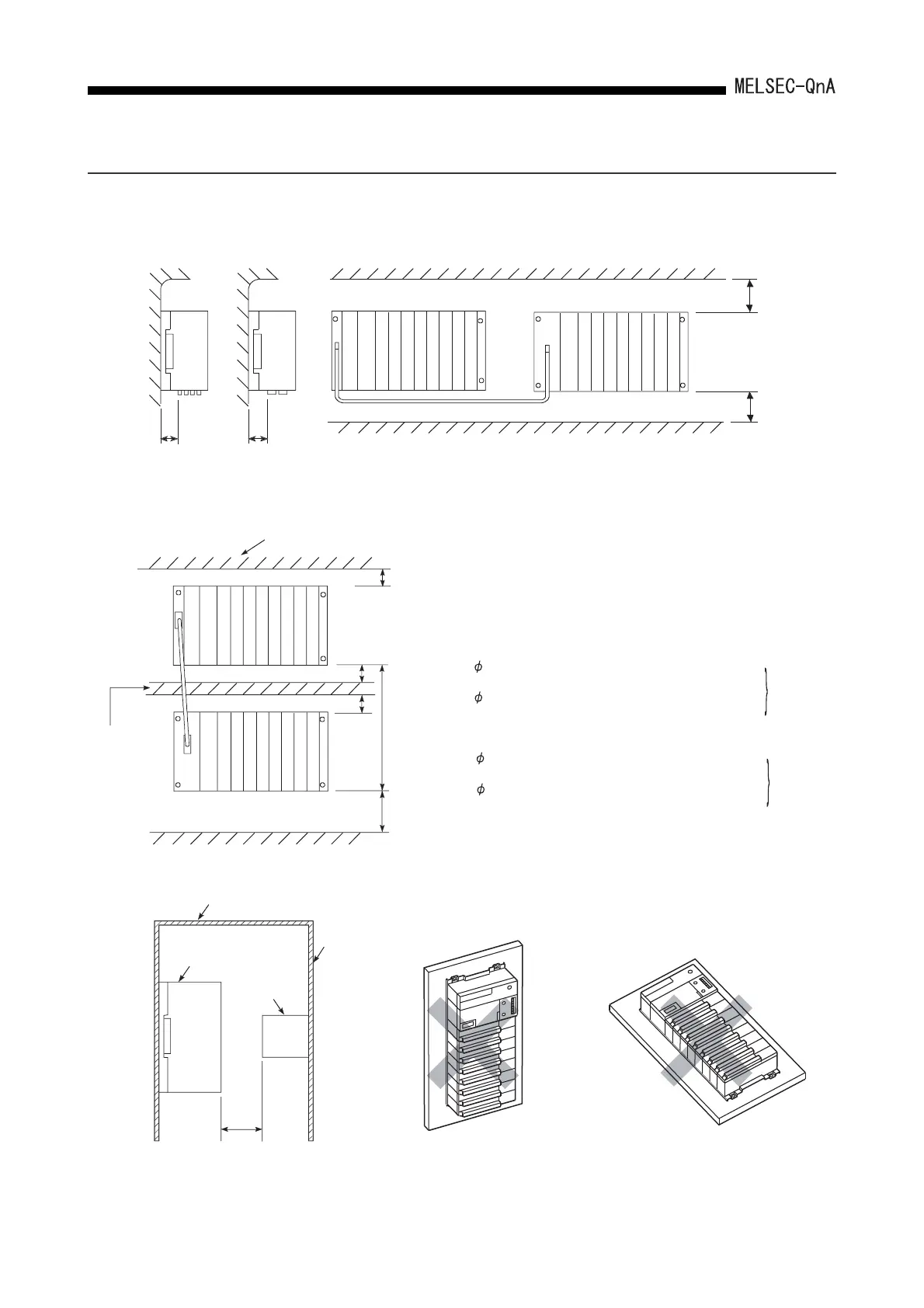
19.4.2 Installation
Installation location of the main base unit and the extension base unit is shown below.
28
*3
39
*1
*3
*2
Indicates the panel top,
wiring duct, or any assembly.
80 mm
(3.15 inch)
or more
Extension base unitMain base unit
For coaxial
data link
For optical
data link
Indicates the panel top, wiring
duct, or any assembly.
Fig. 19.1 Parallel mounting
Main base unit
80 mm
(3.15 inch)
or more
80 mm
(3.15 inch)
or more
Extension base unit
Duct
(max. 50 mm
(1.97 inch))
Fig. 19.2 Serial mounting
Fig. 19.3 Minimum front clearance with
equipment
Fig. 19.4 Vertical mounting
(Not allowed)
Fig. 19.5 Horizontal mounting
(Not allowed)
Panel, etc.
Door
PLC
Contactor,
relay, etc.
100mm (3.94inch)
or more
*1: .....Depends on the length of the extension cable as
indicated below.
*2: .....When no link module is used .......... 50mm (1.97inch) or more
For Type AC06B cable ........... 450mm (17.72inch) or less
For Type AC12B cable ........... 1050mm (41.34inch) or less
For Type AC30B cable ........... 2850mm (112.21inch) or less
100mm
(3.94in
ch)
or more
*3: ..... When the link unit is not used..........50mm (1.97inch) or more
100mm
(3.94in
ch)
or more
When 4.5mm (0.18inch) dia. optical fiber cable or coaxial
cables used ................................100mm (3.94inch) or more
When 8.5mm (0.33inch) dia. optical fiber cable is used
.....................................................130mm (5.19inch) or more
When 4.5mm (0.18inch) dia. optical fiber cable or coaxial
cable is used ..............................100mm (3.94inch) or more
When 8.5mm (0.33inch) dia. optical fiber cable is used
.....................................................130mm (5.19inch) or more
 Loading...

