22.
22 - 13
TROUBLESHOOTING
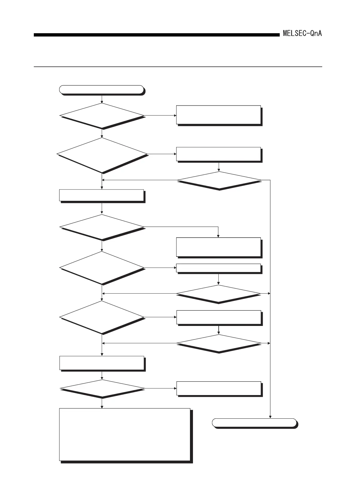
22.2.11 Flow chart used when the CPU module is not started up
The following shows the flow when the CPU module is not started up.
Completed
NO
YES
NO
YES
NO
NO
NO YES
YES
NO YES
NO
YES
YES
NO
YES
The CPU module is not started up.
Is the power supply
module LED ON?
Are all the power of the power
supply modules ON? Is the power supply
module wired correctly?
Try to connect the peripheral device.
Is it available
to communicate with
the peripheral device?
Is the extension cable
connected to the incorrect
direction? (Connected IN and
IN, or OUT and OUT?)
Is the RUN/STOP key
switch of the CPU
module at RESET?
at RESET
Not at RESET
Switch the power supply module and
confirm the LED lights.
Is CPU module started up?
See "Flowchart for actions when
the "POWER" LED is turned OFF".
Review the wiring and turn ON all the
power supply .
Is CPU module started up?
Is CPU module started up?
Is CPU module started up?
Make the PLC diagnosis, and execute
the troubleshooting according to the
result.
Connect the extension cable.
Switch the RUN/STOP key switch
to RUN.
Hardware error of the power supply
module
Possible hardware errors are described below.
1) CPU module
2)Main base unit, Extension base unit
3)Extension cable
4)Network module (Only when installed)
For the malfunctioning module even after executed the serial
operation check from the minimum system, please consult
your local Mitsubishi service center or representative,
explaining a detailed description of the problem.
(Refer to Section 22.2.2.)
 Loading...

