17 - 10
17. BASE UNIT AND EXTENSION CABLE
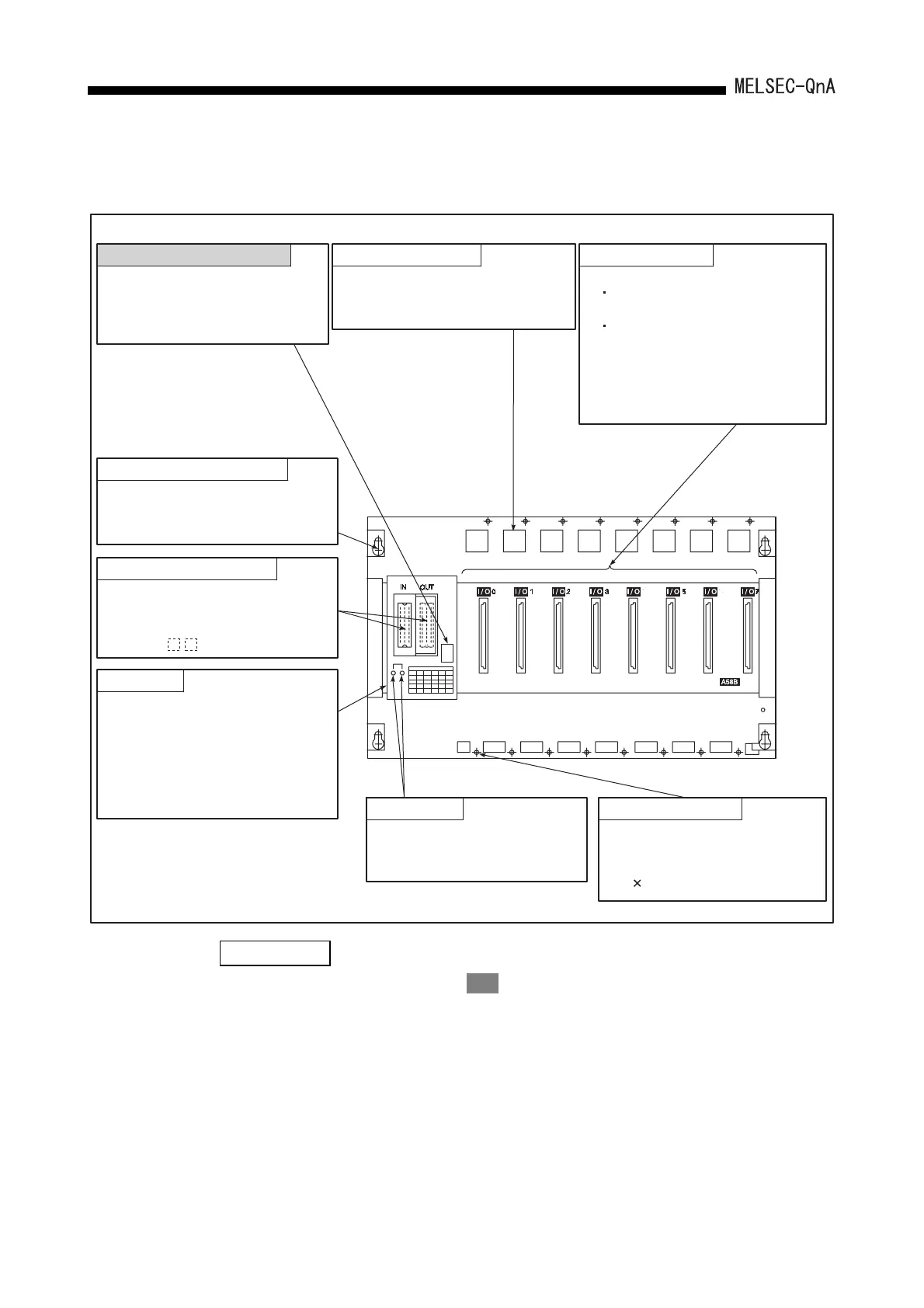
(3) Extension base units (A52B, A55B, A58B)
REMARK
The item indicated by shading must be set before installing the base unit and
starting operation.
Module connector
Connectors for loading I/O
modules.
To prevent dust from entering
the connector with no module
installed, attach the supplied
blind cap, blank cover (AG60),
or dummy module (AG62).
Module fixing cutout
The projection and hook on a rear
of a module are inserted for fixing
the module.
Stage number setting switch
Switch for setting the stage number
of the extension base unit. (located
under the base cover) For the
stage number setting procedure,
see
Guide hole for base installation
A bell-shaped hole used to install
the base unit to a control panel.
(For M5 screw)
FG terminal
Ground terminal connected to the
shielding pattern on the printed
wiring board. (located under the
base cover.)
Module fixing screw
Modules can be fixed with a
screw in addition to the module
fixing hook. Screw size:
M4 0.7 screw
Connector for sending and receiving
signals to and from the extension
base unit. Connect the extension
cable (AC B).
Extension cable connector
Base cover
A protective cover for the connector
for the extension cable. To connect
with another extension base unit, the
part enclosed by a groove at the
portion marked "OUT" on the base
cover must be removed with a tool
such as nippers.
Section 17.6.
 Loading...

