20 - 8
20. EMC AND LOW VOLTAGE DIRECTIVES
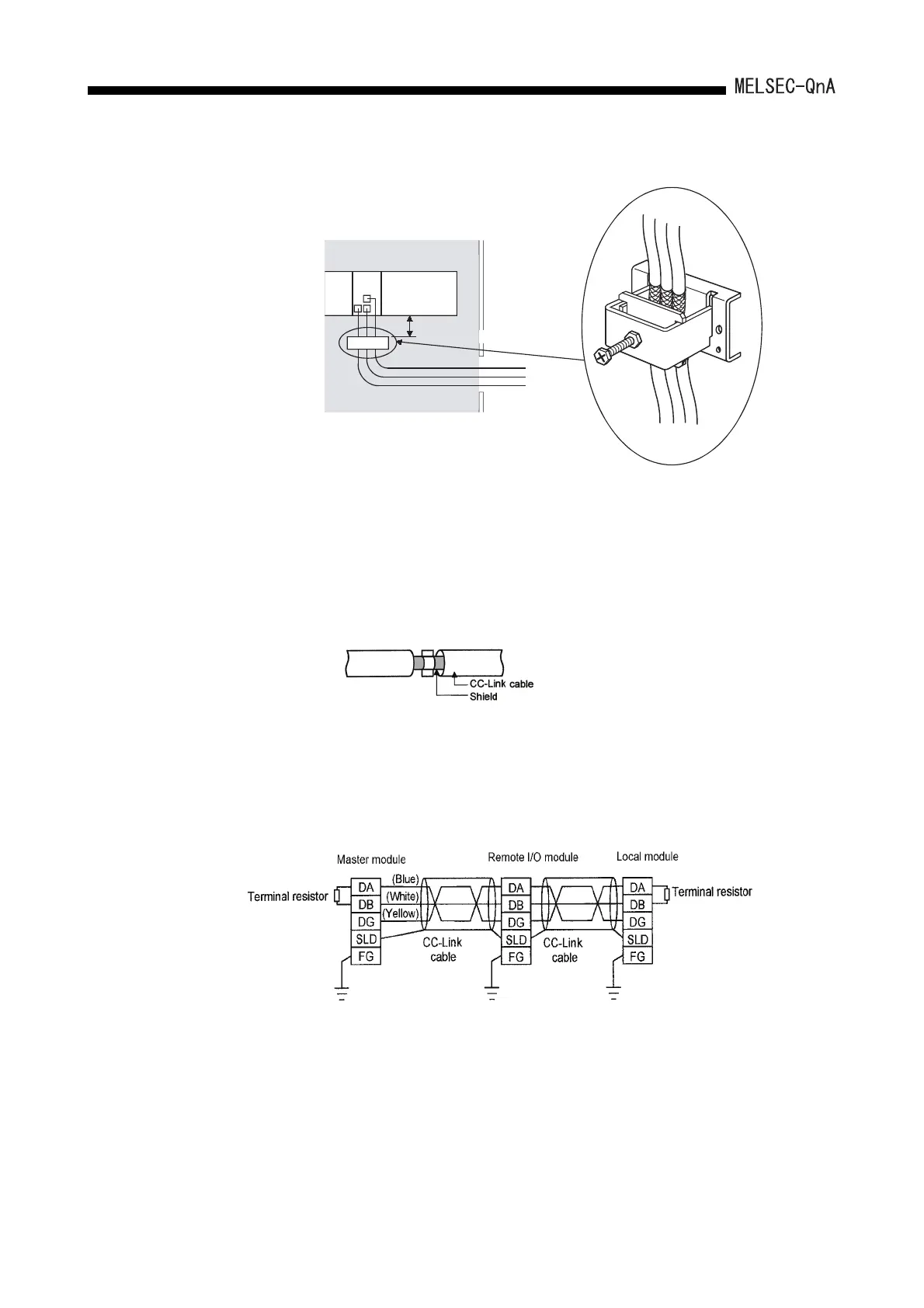
(d) Cable clamp position
(6) CC-Link module
(a) Be sure to ground the shield of the cable that is connected to a CC-Link module
close to the exit of the control panel or to any of CC-Link stations within 30cm
(11.81inch) from the module or stations.
The CC-Link dedicated cables are shielded cables. As shown in the illustration
below, remove a part of the outer sheath and ground it to the widest possible
area.
(b) Always use the specified CC-Link dedicated cable.
(c) Connect the CC-Link module and each CC-Link station to the FG line inside the
control panel with the FG terminals as shown below.
[Simplified diagram]
(d) Power line connecting to the external power supply terminal (compliant with I/O
power port of CE standard) should be 30m (98.43 ft.) or less.
Power line connecting to module power supply terminal (compliant with main
power port of CE standard) should be 10m (32.81 ft.) or less.
(e) A power line connecting to the analog input of the following modules should be
30cm or less.
• AJ65BT-64RD3
• AJ65BT-64RD4
• AJ65BT-68TD
AD75
AD75CK
Inside
control panel
20 to 30cm
(7.87 to 11.81inch)
 Loading...

