22 - 48
22. TROUBLESHOOTING
Calculation example for Example 4
• Voltage V
TB between the terminal and common is as follows:
Because the condition for the OFF voltage ( 6[V]) is not satisfied, the input does not
turn off. To correct this, connect a resistor as shown below.
• Calculation of resistance of connected resistor R
The voltage of AX40 between the terminals must be reduced to within 6[V]. The
current for reducing the voltage between the terminals to within 6 [V] is:
Therefore, resistor R for flowing current I of 5[mA] has to be connected.
• Resistance of the connected resistor R is obtained in the following equations.
Suppose that the resistance R is 2[k ].
The power capacity W of the resistor when the switch turned on is:
• Because the resistance is selected so that the power capacity is three to five times
the actual power consumption, 1.5 to 2 [W] should be selected. From the above,
the resistor to be connected across the terminal in question and COM is 2[k ] 1.5
to 2[W].
Situation Cause Countermeasure
Example 5
Input signal does not
turn OFF.
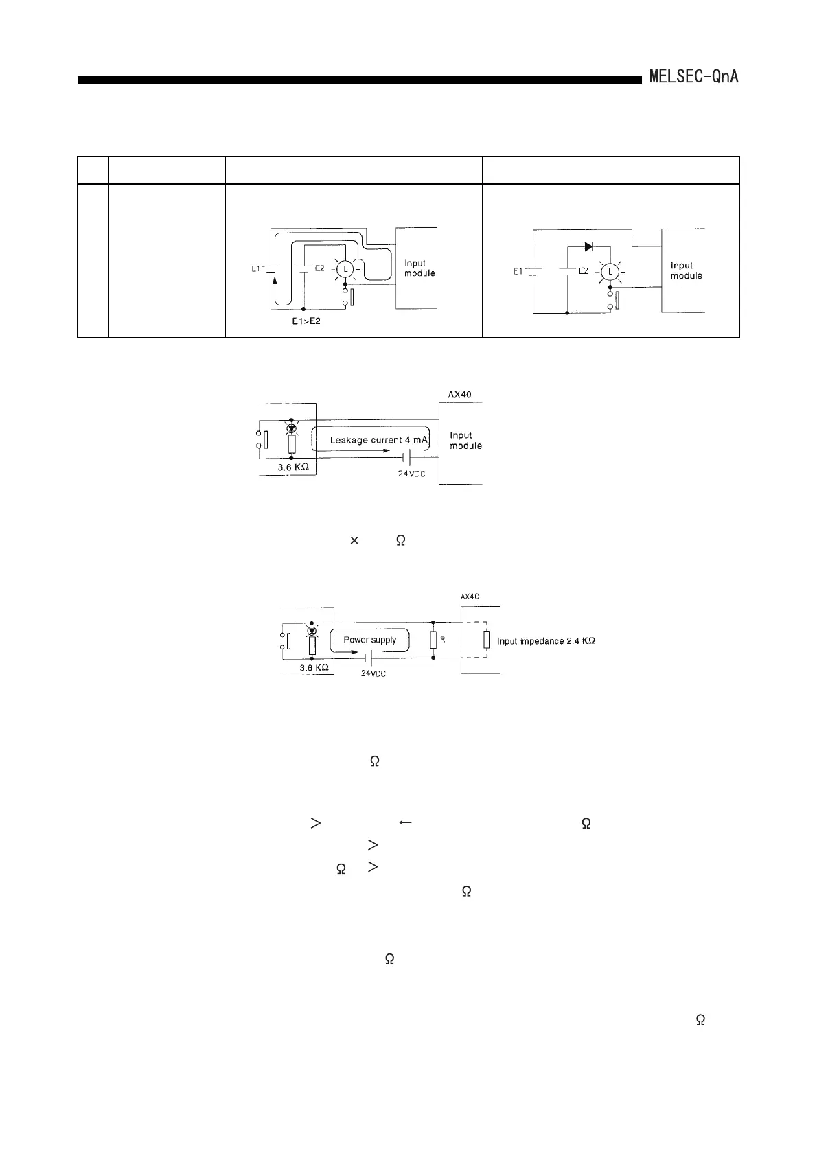
• Sneak path due to the use of two power supplies.
• Use only one power supply.
• Connect a diode for a sneak path. (Figure below).
If a switch with LED indication is
connected to theAX40 and leak current of
4mA is generated
VTB = 4[mA] 2.4[k ] = 9.6[V] (Ignore the voltage drop caused by the LED.)
(24 - 6[V])/3.6[k ]=5mA
6[V]/R 5 - 2.5[mA] 6[V]/Input impedance 2.4[k ]
6[V]/2.5mA
R
2.4[k ]
R
W = (Applied voltage)
2
/R
W = (26.4[V])
2
/2[k ] = 0.348[W]
 Loading...

