Controlling Operation and Outputting Data with the Sensor's Standard Parallel Connection
FQ2 User’s Manual
247
8
Controlling Operation and Outputting Data
with a Parallel Connection
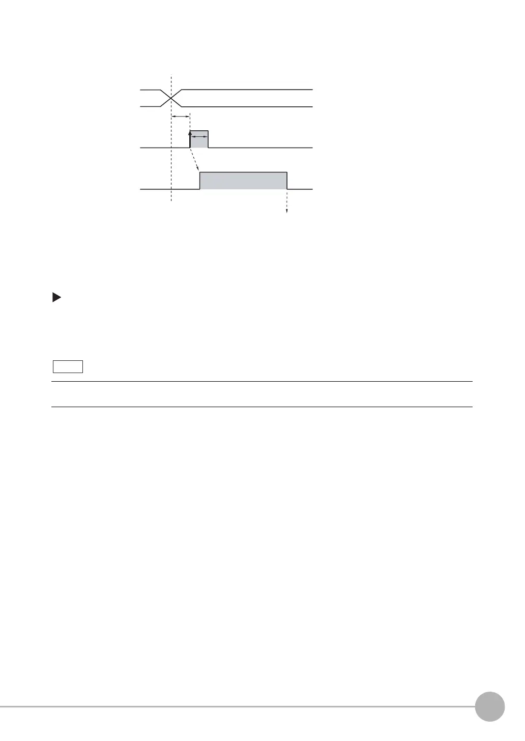
Timing Chart
Settings
[In/Out] − [I/O setting] − [I/O setting] − [Input] − [Input mode]
The scene numbers that can be used depend on the input mode.
[Standard mode] (default): Scene 0 to 31
[Expanded mode]: Scene 0 to 15
1 Specify the scene number
with the IN0 to IN4 signals.
(Standard Mode)
2 Turn ON the IN5 signal while
the BUSY signal is ON to
change the scene to the
specified scene.
3 The BUSY signal turns ON
while the scene is being
switched.
Even in Expanded Mode, you can use menu commands or Ethernet no-protocol commands to change to
scenes 0 to 31.
OFF
ON
OFF
ON
*1: In Expanded Mode, specify scene numbers 0 to 15 using the
IN0 to IN3 signals.
End scene change
Start scene change
BUSY signal
IN5 signal
ON for 1 ms min.
Allow 5 ms min. and then turn ON IN5.
Scene number 0 to 31
IN0 to IN4 signals
(in Standard Mode)
*1

 Loading...


